
Golf Mk6
 Caution
|
|
|
|
|
|
|
|
|
|
|
|
 Note
Note
|
|
|
|
|
|
Note
|
|
|
|
|
|
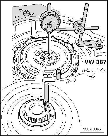
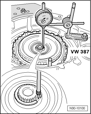
| Determined size for new retaining ring | New retaining ring |
| 2.27 mm | 2.3 mm |
| 2.24 mm | 2.2 mm |
Note
|
|
Note
|
|
|
|
|
|