
Golf Mk6
| Dismantling and assembling output shaft |
| Special tools and workshop equipment required |
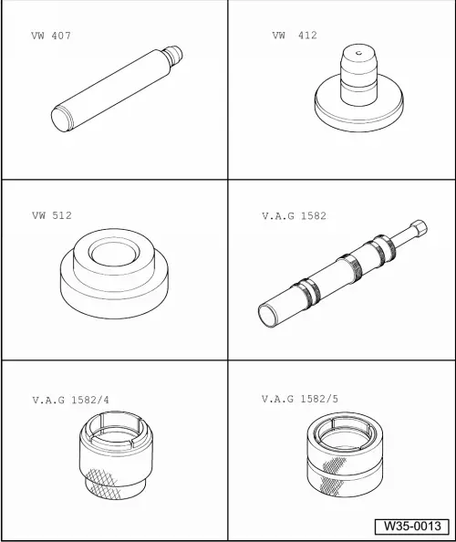
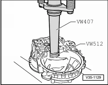
| t | Press tool -VW 407- |
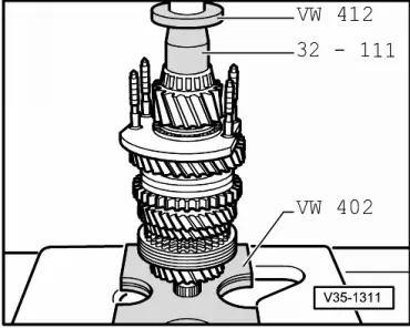
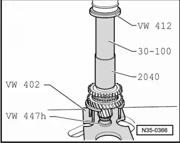
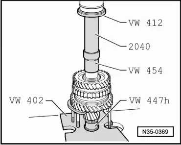
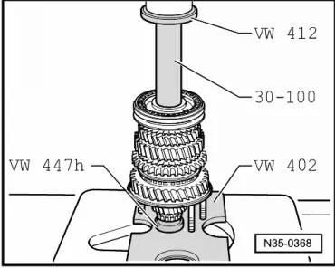
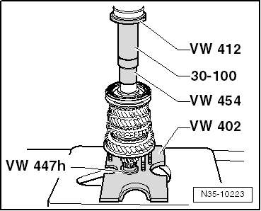
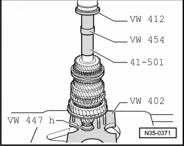
| t | Press tool -VW 412- |
| t | Thrust pad -VW 512- |
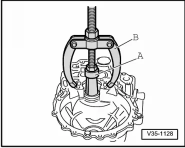
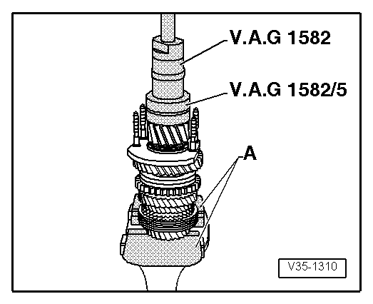
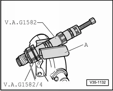
| t | Puller -V.A.G 1582- |
| t | Adapter -V.A.G 1582/4- |
| t | Adapter -V.A.G 1582/5- |
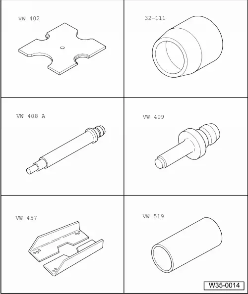
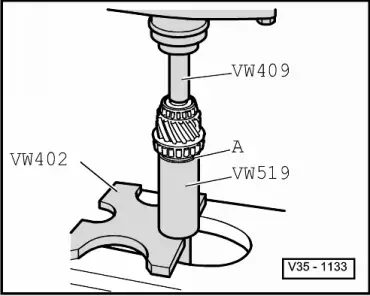
| t | Pressure plate -VW 402- |
| t | Thrust piece -32 - 111- |
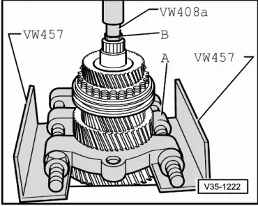
| t | Press tool -VW 408 A- |
| t | Press tool -VW 409- |
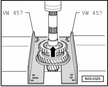
| t | Support rails -VW 457- |
| t | Tube -VW 519- |
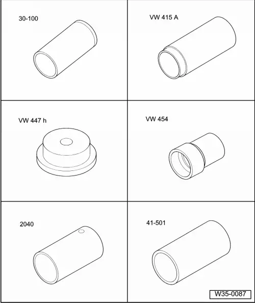
| t | Drift sleeve -30 - 100- |
| t | Tube -VW 415 A- |
| t | Thrust pad -VW 447 H- |
| t | Thrust piece -VW 454- |
| t | Tube -2040- |
| t | Drift sleeve -41 - 501- |
|
|
|
|
|
|
|
|
|
|
|
|
|
|
|
|
|
|
 Note
Note
|
|
|
|
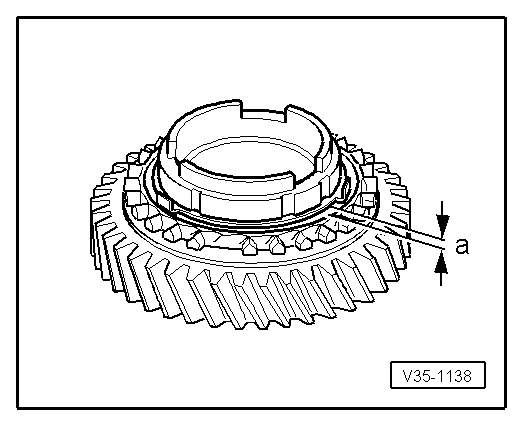
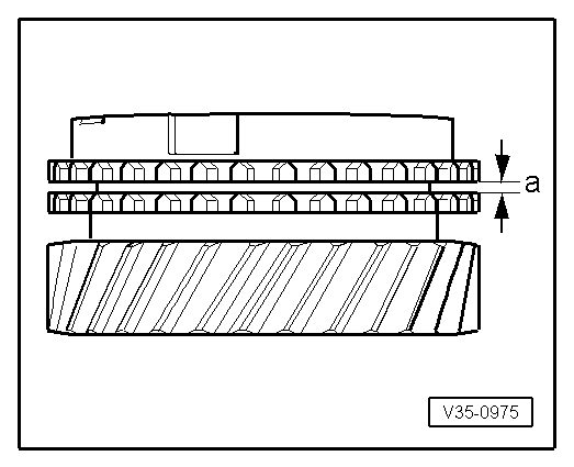
| Gap -a- | Installation dimension | Wear limit |
| 1st and 2nd gears | 0.75 … 1.25 mm | 0.3 mm |
|
|
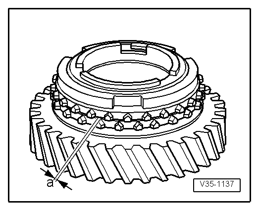
| Gap -a- | Installation dimension | Wear limit |
| 1st and 2nd gears | 1.2 … 1.8 mm | 0.5 mm |
|
|
|
|
|
|
|
|
|
|
|
|
|
|
|
|
|
|
|
|
| Gap -a- | Installation dimension | Wear limit |
| 1st gear 3rd gear 4th gear | 1.0 ... 1.7 mm 1.0 ... 1.7 mm 1.0 ... 1.7 mm | 0.5 mm |
|
|
|
|
|
|
|
|
|
|
|
|
|
|