volkswagen Workshop Repair Guides

Volkswagen Workshop Service and Repair Manuals

Separating engine and gearbox > < Removing and installing engine
Removing engine (Golf, Polo)
   
Removing engine (Golf, Polo)
Special tools and workshop equipment required
t  Lifting tackle -3033-
t  Hose clamps, up to 25 mm  -3094- (only for vehicles with manual gearbox)
t  Torque wrench -V.A.G 1331-
t  Torque wrench -V.A.G 1332-
t  Stepladder -VAS 5085-
t  Workshop crane -VAS 6100-

   
t  Drip tray for workshop hoist -VAS 6208-
  W00-10228
t  Spring-type clip pliers -VAS 6362-
  W00-10427
t  
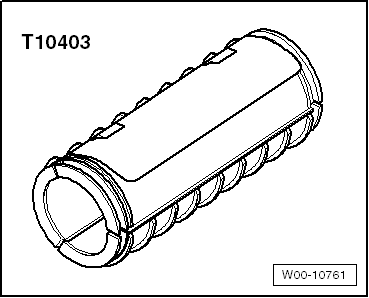
Transportation lock -T10403-
t  
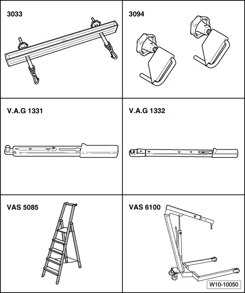
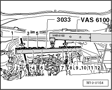
Engine bung set -VAS 6122- (not shown)
  Note
t  Before carrying out further work, disconnect battery earth strap. Check whether a coded radio is fitted. Obtain anti-theft coding if necessary.
t  The engine is removed forwards together with the gearbox.
t  All cable ties that are opened or cut through when the engine is removed must be renewed in the same position when the engine is installed.
  WARNING
When doing any repair work, especially in the engine compartment, pay attention to the following due to the cramped conditions:
t  
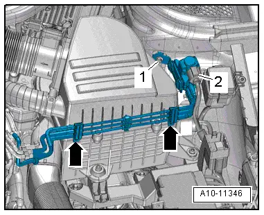
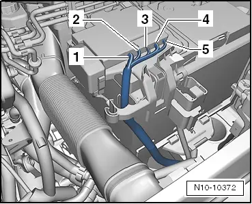
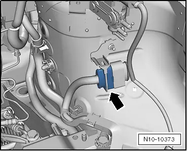
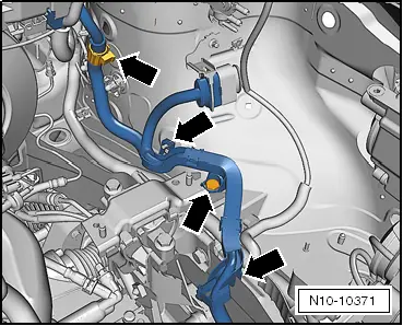
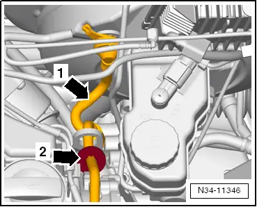
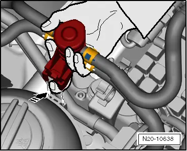
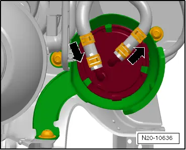
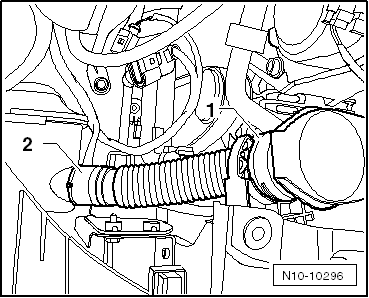
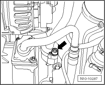
Route all the various lines and electrical wiring so that they are in their original positions.
t  e.g. for fuel, hydraulics, activated charcoal filter system, coolant and refrigerant, brake fluid, vacuum.
t  Ensure that there is sufficient clearance to all moving or hot components.
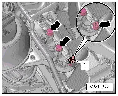
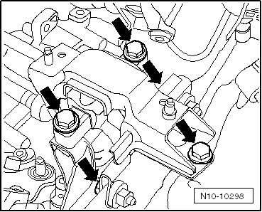
»Carry out the following work sequence«
Removing
–  Remove engine cover panel → Chapter.
–  With ignition switched off, disconnect earth strap from battery. → Electrical system; Rep. gr.27.
Polo
  W00-10761
–  Disconnect electrical connector -2-.
–  Remove bolt -1-.
–  Expose vacuum hoses -arrows- and place charge pressure control solenoid valve -N75- on the engine.
Continuation for all vehicles
–  Remove air filter housing with air mass meter and connecting pipe .
  A10-11346
–  Detach vacuum line -arrow- on brake servo.
–  Remove noise insulation → General body repairs, exterior; Rep. gr.50
–  Drain coolant → Chapter.
Vehicles with air conditioner
–  Extract refrigerant from air conditioning system → Heating, air conditioning system; Rep. gr.87.
  N10-10466
–  Unscrew refrigerant lines -arrow- at lock carrier → Heater, air conditioning system; Rep. gr.87.
Continuation for all vehicles
–  Remove lock carrier → General body repairs, exterior; Rep. gr.50.
  N10-10293
–  Detach vacuum line -2- from vacuum pump -1-.
Golf
–  Separate connectors.
t  -1-Exhaust gas temperature sender 1 -G 235-
t  -2-Exhaust gas temperature sender 4 -G 648-
  N15-10448
t  -3-Lambda probe -G 39-
  N26-10333
–  Disconnect connector for exhaust temperature sender 3 -G 495--1- (secured behind bracket).
–  Guide lines out of brackets on plenum chamber bulkhead and on turbocharger.
–  Remove windscreen wiper arms and plenum chamber cover → Electrical system; Rep. gr.92.
–  Remove plenum chamber bulkhead → General body repairs; Rep. gr.50.
–  Remove engine control unit from its bracket .
  N26-10334
–  Release connector for engine wiring harness -arrow- and pull off from engine control unit.
  N10-10290
–  Open catch -A- of passage in plenum chamber bulkhead and pull top part out upwards.
  N10-10291
–  Pull off vacuum hoses -1- and -2- for charge air control.
  N10-10286
–  Unbolt positive cable -arrow- from starter at central electrics and lay cable on engine.
  N10-10253
–  Separate connectors -1- and -2-.
–  Remove engine control unit wiring harness from cable duct.
–  Place engine wiring harness on engine.
  N10-10288
–  Pull connector -2- off pressure differential sender -G 505-.
–  Unscrew bolts -3 + 4-.
  N26-10526
–  Unclip lines for pressure differential sender -G 505- out of upper toothed belt guard together with bracket -1-.
–  Lay pressure differential sender -G 505- aside to rear together with lines.
  N15-10495
–  Unscrew bolts -1- for pressure differential sender -G 505- bracket.
–  Remove pressure differential sender -G 505- bracket.
–  Remove fuel filter with bracket and place fuel filter on engine. → Fuel supply; Rep. gr.20
–  Catch any escaping fuel.
  N26-10526
–  Unscrew bolt -arrow-, and lay filler neck for windscreen waster system reservoir aside.
–  Remove lower sections of wheel housing liners on left and right.
Polo
  N10-10284
–  Unbolt positive cable -1- at positive distributor on battery.
–  During further procedure, lay cable down on engine.
–  Remove air filter housing with air mass meter and connecting pipe → Chapter.
  N10-10372
–  Disconnect connectors -arrow-.
  N10-10373
–  Carefully loosen engine wiring harness at its fastening points -arrows-.
–  Place engine wiring harness on engine.
  N10-10371
–  In order to ensure that the vacuum hose -arrow 1- from the brake servo to the engine is not damaged, you must remove it → Rep. gr.47.
  N34-11346
Pre-heater line -arrow 2- is not necessarily installed.
–  Separate connectors at engine control unit → Chapter.
–  Separate connectors.
t  -1-Exhaust gas temperature sender 1 -G 235-
t  -2-Exhaust gas temperature sender 3 -G 495-
t  -3-Exhaust gas temperature sender 4 -G 648-
  N15-10539
t  -4-Lambda probe -G 39-
  N26-10416
–  Disconnect electrical connector -2- at pressure differential sender -G 505-.
–  Unscrew bolt -3- from pressure differential sender -G 505- bracket.
–  Lay pressure differential sender -G 505- aside to rear together with lines.
  N26-10525
–  Separate fuel supply line and return line at fuel transfer point.
The procedure for this is explained in → Fuel supply system; Rep. gr.20
–  Catch any escaping fuel.
  N20-10436
–  Using a finger, release lug from fuel pre-heater valve.
–  Pull fuel pre-heater valve upwards out of coolant expansion tank guide.
  N20-10638
–  Unclip fuel filter from lower part of fuel filter.
–  Take fuel filter out upwards.
–  Place fuel filter and fuel hoses together with fuel pre-heater valve on engine.
–  Remove fuel filter lower part → Fuel supply; Rep. gr.20.
  N20-10636
–  Filler neck: Unclip windscreen washer system reservoir -1-.
–  Filler neck: Unclip windscreen washer system reservoir -2-.
Vehicles with air conditioning system:
  N10-10296
–  During further procedure, unscrew securing bolt for refrigerant line -arrow- at air conditioner compressor → Air conditioning system; Rep. gr.87.
–  Pull off refrigerant line at air conditioner compressor and lay it aside without kinking.
Continuation for all vehicles:
–  Remove coolant expansion tank and lay down on engine.
  N10-10287
–  Unscrew bolt -arrow- (attached), unscrew intake hose -A- clockwise out of its bracket and remove.
  N10-10285
–  Disconnect coolant hoses from heat exchanger for heater; lifting retaining clips -1, 2- to do so.
Vehicles with dual clutch gearbox:
–  Remove gear change mechanism from gearbox → 7-speed dual clutch gearbox; Rep. gr.34.
  A10-11348
–  Release catch on mechatronic connector by pulling -arrow- and pull connector off.
Vehicles with manual gearbox:
–  Remove gear change mechanism from gearbox → Manual gearbox; Rep. gr.34.
  N34-10956
–  Remove bolt -3-.
  A30-10133
–  Remove bolts -arrows- and lay clutch slave cylinder aside. Do not open hydraulic system.
–  Guide clutch slave cylinder under strut -1-.
Continuation for all vehicles:
–  Unbolt earth cable on gearbox.
–  Disconnect all connectors between starter, gearbox and body.
  A10-1630
–  Remove bolt -1-.
  N26-10528
–  Disconnect connector on oil level and oil temperature sender -G266-.
  A17-0215
–  Remove right drive shaft cover.
–  Remove drive shafts at gearbox → Running gear, axles, steering; Rep. gr.40.
–  Tie up drive shafts as high as possible.
  N17-10184
–  Remove bolts -2…3-.
  A10-1578
–  Remove securing clamp -1- between particulate filter and turbocharger.
  N26-10372
–  If necessary, securing clamp -2- between particulate filter and turbocharger must also be removed from above.
Golf
  A26-10721
–  Loosen securing nuts above particulate filter bracket -1- using ratchet wrench, 13 mm -T10384-.
–  Unscrew securing nuts -2- for particulate filter bracket on crankcase.
Polo
  A26-10723
–  Unscrew bolts -1- and nuts -2-.
–  Remove particulate filter bracket.
Continuation for all vehicles:
–  Push particulate filter aside and fix it in position on plenum chamber bulkhead using suitable means.
  Note
Check that all hose and line connections between engine, gearbox and body have been detached.
  N26-10535
–  Use lifting tackle -3033- and workshop crane -VAS 6100- to support »engine/gearbox assembly« in installation position.
Vibration damper end:
l  Position 2.
Flywheel end:
l  Position 8.
Golf
  M10-0154
–  Unscrew securing bolts -arrows- of assembly mounting at engine.
  N10-0437
–  Unscrew securing bolts -arrows- of assembly mounting at gearbox.
Polo
Remove complete engine assembly mounting → Chapter.
  A10-1634
–  Unscrew nut -1- and expose earth line
Remove assembly mounting at gearbox.
  A10-11338
–  To do this, undo bolts -arrows- for support arm of engine mounting.
Continuation for all vehicles:
  Note
Carefully guide »engine/gearbox assembly« when removing to avoid damage to body.
–  Slightly lift »engine/gearbox assembly« and remove forwards.
Secure engine on engine and gearbox support -VAS 6095- to carry out repairs → Chapter.
  N10-10298

Separating engine and gearbox > < Removing and installing engine