volkswagen Workshop Repair Guides

Volkswagen Workshop Service and Repair Manuals

Charge air system > < Removing and installing turbocharger
Removing and installing turbocharger (Golf)
Special tools and workshop equipment required
   
t  Tool set, 17 mm -T10395-
  W00-10767
t  Torque wrench -V.A.G 1331-
  W00-0427
t  Used oil collection and extraction unit -V.A.G 1782-
»Carry out the following work sequence«
Removing
→ Chapter „Safety precautions“
→ Chapter „Rules for cleanliness“
–  Remove engine cover panel → Chapter.
  W00-10211
–  Remove air filter housing with bracket → Chapter.
–  With ignition switched off, disconnect earth strap from battery. → Electrical system; Rep. gr.27.
  A23-10314
–  Remove crankcase breather hose -1- from cylinder head cover; press release buttons for this.
–  Free vacuum hoses -arrows-.
–  Unscrew bolt -2-, swing intake hose with intake connection to rear and pull off of turbocharger.
–  Remove plenum chamber bulkhead → General body repairs; Rep. gr.50.
  Note
Disregard -item 1-.
  A21-10487
–  Detach vacuum line -arrow- from brake servo and vacuum pump.
–  Remove heat shield sleeve from position sender for charge pressure positioner -G581-.
  N10-10466
–  Disconnect electrical connector -1- at position sender for charge pressure positioner -G581-.
–  Pull vacuum hose -2- from turbocharger vacuum unit.
–  Separate vacuum hose -3-.
  A21-10338
–  Free electrical connector -3- for exhaust temperature sender 1 -G 235- and electrical line.
Loosen particulate filter.
  A26-10696
–  Unscrew bolt -1-.
  N26-10528
–  Unscrew securing clamp -2- between particulate filter and turbocharger.
  Note
Disregard -item 1, 2-.
  A26-10721
–  Remove bolts -arrows-.
–  Take off pulsation damper -2-.
  A21-10478
–  Unscrew bolts and remove pipes -A- for exhaust gas recirculation.
Vehicles with supplementary heater or auxiliary heater
–  Disconnect coolant lines → Rep. gr.87.
All other vehicles continued
  N15-10443
–  Unscrew securing nuts -2- for particulate filter bracket on crankcase.
  A26-10723
–  Unscrew bolts -1, 2- and banjo bolts -4, 5-, and remove turbocharger support with oil supply line.
  Note
Disregard -item 3-.
  A21-10494
–  Unscrew bolts -arrows- and remove heat shield.
  A21-10480
–  Unscrew nuts -arrows- and pull turbocharger with exhaust manifold off cylinder head.
  A21-10481
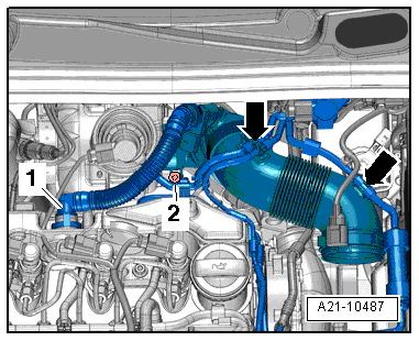
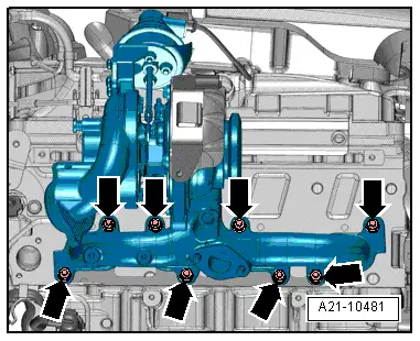
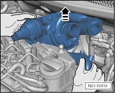
–  Carefully remove turbocharger from above in direction of gearbox.
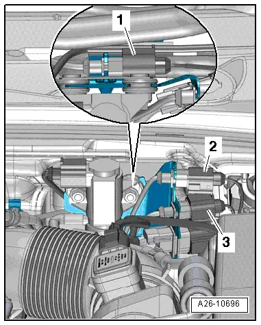
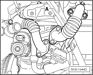
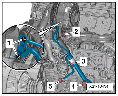
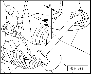
Installing
Specified torques:
t  Assembly overview - turbocharger → Chapter
t  Coolant lines → Auxiliary heater; Rep. gr.82
  Caution
Before installing, check whether decoupling element of oil return line is bent and thus stretched. If this is the case, micro cracks can have formed and may cause leakage. If necessary, renew oil return line of turbocharger before installing.
–  Install in reverse order. In the process, note the following:
  Note
t  Renew seals, gaskets, O-rings and self-locking nuts.
t  Fill turbocharger with engine oil at connection for oil supply line.
t  Hose unions and air intake pipes/hoses must be free of oil and grease when installing.
t  Secure all hose connections with the correct type of hose clips (same as original equipment) → Electronic parts catalogue.
t  After installing turbocharger, run engine for about 1 minute at idling speed to ensure that oil is supplied to turbocharger.
t  Reinstall heat insulation sleeves in the original positions when installing.
  N21-10518
Installation position of exhaust gas temperature sender with angled cable guide
  Note
When installing the exhaust temperature sender with angled cable guide, adhere to dimension -a- of 3 … 5 mm from the turbocharger support threaded connection.
  N21-10161

Charge air system > < Removing and installing turbocharger