
Golf Mk6
| Coolant hose schematic diagram, vehicles without 4/2-way valve, engine codes CBAA, CBBB, CBAB, CBBA, CBDB, CBDC, CBAC, CBDA |
 WARNING
|
 Note
Note| t | When the engine is warm, the cooling system is under pressure. If necessary, release pressure before beginning repair work. |
| t | Hoses are secured with spring-type clips. In case of repair, only use spring-type clips. |
| t | Hose clip pliers -VAS 6340- are recommended to install spring-type clips. |
| t | When installing coolant hoses, route stress-free so that they do not come into contact with other components (observe markings on coolant connection and hose). |
| Test for leaks in cooling system using cooling system tester -V.A.G 1274/- and adapter for expansion tank -V.A.G 1274/8- and adapter for sealing cap -V.A.G 1274/9-. |
Note| As of week 22/09 a 4/2-way valve has been introduced; this contains the thermostat and ensures an improved flow of coolant through the cylinder head. Schematic diagram for vehicles with 4/2-way valve → Chapter. |
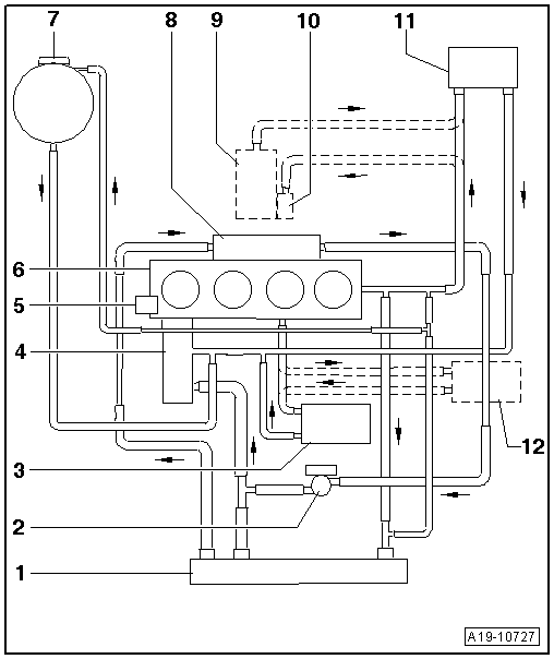
| 1 - | Radiator |
| 2 - | Coolant circulation pump -V178- |
| 3 - | Engine oil cooler |
| 4 - | Thermostat |
| 5 - | Coolant pump |
| 6 - | Cylinder head/cylinder block |
| 7 - | Expansion tank |
| 8 - | Radiator |
| q | For exhaust gas recirculation. |
| 9 - | Supplementary heater/auxiliary heater |
| q | Depending on equipment. |
| 10 - | Circulation pump -V55- |
| q | Depending on equipment. |
| 11 - | Heat exchanger for heater unit |
| q | With quick-release coupling. |
| 12 - | Gearbox oil cooler |
| q | Only vehicles with dual clutch gearbox/automatic gearbox. |