| –
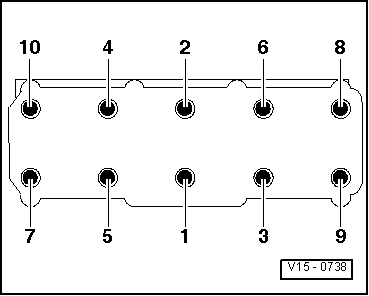
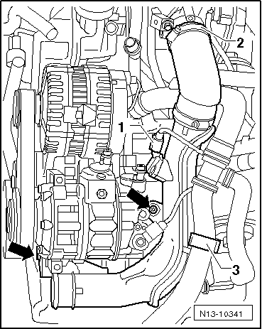
| Maintain sequence when loosening cylinder head bolts. |

Note | t
| A second mechanic is required for the removal of the cylinder head. |
| t
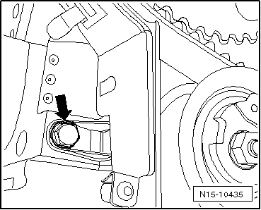
| The toothed belt tensioning roller is pulled off the stud when the cylinder head is lifted out. |
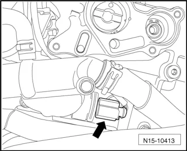
| t
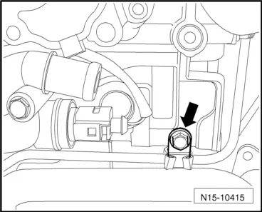
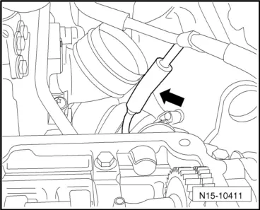
| The oil return line of the turbocharger is pulled out of the support when the cylinder head is lifted out. |
| –
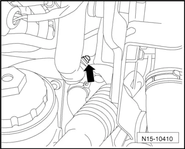
| First lift cylinder head on gearbox side and guide it out of toothed belt guard. Prevent toothed belt tensioning roller from falling down. |
| –
| Place cylinder head down taking care not to bend oil return line. If necessary, place a piece of wood under exhaust manifold. |
Note | t
| Always renew cylinder head bolts. |
| t
| In cases of repair, carefully remove gasket remains from cylinder head and cylinder block. Ensure that no long scores or scratches are made on the surfaces. When using abrasive paper do not use a grade less than 100. |
| t
| Carefully remove emery and abrasive remains. |
| t
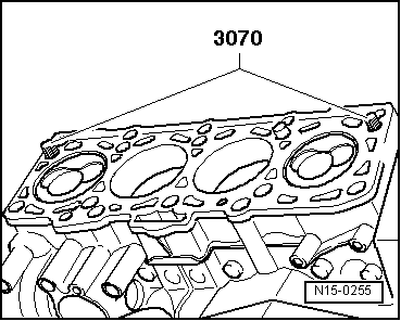
| Do not remove new cylinder head gasket from packaging until it is ready to be fitted. |
| t
| Handle gasket very carefully. Damage to the silicone coating or the indented area will lead to leaks. |
| –
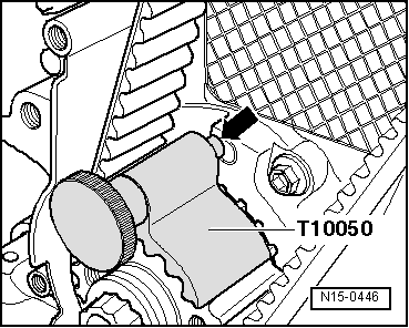
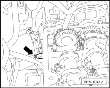
| Before fitting cylinder head, remove crankshaft stop -T10050- and turn crankshaft opposite direction of rotation until all pistons are nearly uniformly below TDC. |
| –
| Cylinder head gasket must lie with identification facing upwards. |
|
|
|


 WARNING
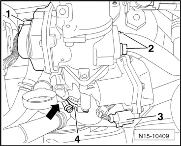
 Caution