volkswagen Workshop Repair Guides

Volkswagen Workshop Service and Repair Manuals

Removing and installing cylinder head cover > < Assembly overview - cylinder head
Removing and installing cylinder head
   
Removing and installing cylinder head
Special tools and workshop equipment required
t  Guide pins -3070-
t  Diesel injection pump locking pin -3359-
t  Crankshaft stop -T10050-
t  Counterhold tool -T10051-
t  Puller -T10052-
t  Bit XZN 10 -T10385-

   
t  Torque wrench -V.A.G 1331-
t  Torque wrench -V.A.G 1332-
t  Drip tray for workshop hoist -VAS 6208-

  Note
t  Read anti-theft radio code as the next work step requires the earth strap of the battery to be disconnected.
t  All cable ties which are opened or cut through when cylinder head is removed must be renewed/replaced in the same position when the cylinder head is installed.
  WARNING
When doing any repair work, especially in the engine compartment, pay attention to the following due to the cramped conditions:
t  Route lines of any kind so that the original routing can be restored.
t  Ensure that there is sufficient clearance to all moving or hot components.
Removing
–  With ignition switched off, disconnect earth strap from battery. → Electrical system; Rep. gr.27.
–  Remove engine cover → Chapter.
–  Remove air filter housing → Chapter.
–  Remove battery and battery tray → Electrical system; Rep. gr.27.
–  Remove cowling together with radiator fan -V7- and radiator fan on right of radiator -V35- → Chapter.
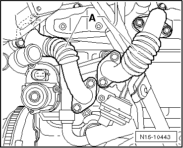
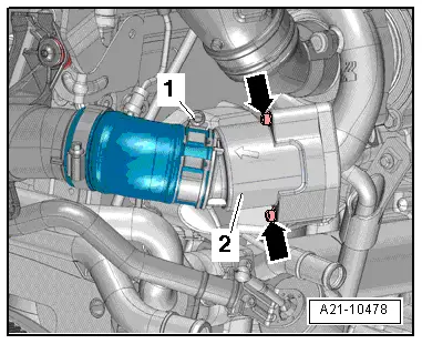
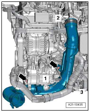
–  Remove connecting hose on »cold side« → Item of charge air cooler.
–  Remove cylinder head cover → Chapter.
   
–  Pull off connector from throttle valve control element -J338--2-.
–  Unscrew bolt from oil dipstick connection -4-.
–  Pull vacuum pipe off the vacuum pump.
  N15-10502
–  Unscrew bolts -2, 5- and -arrows-.
–  Free electrical wiring and hoses on left air pipe using removal lever -80 - 200-.
–  Loosen hose clamp -3- and remove left air pipe.
  A21-10493
–  Unscrew bolts -arrows- and remove pulsation damper -2-.
–  Remove noise insulation → General body repairs, exterior; Rep. gr.66.
–  Drain coolant → Chapter.
–  Unplug electrical connector -4- from coolant temperature sender -G62-.
  A21-10478
–  Pull coolant hoses off connection. To do this, loosen hose clamps -1- and -2-.
  A19-10992
–  Unplug electrical connector -1- from oil pressure switch -F1-.
–  Remove bolt -arrow-.
–  Pull off vacuum hose -2-.
  A15-10799
–  Remove electrical connector -3- from bracket and disconnect.
–  Free electrical lines on turbocharger.
  A26-10696
–  Unscrew securing bolts -arrows- from charge air pipe and detach connector from charge pressure sender -G31--1-.
  A21-10435
–  Open clip -2-, expose coolant hose -3- and remove charge air pipe.
  Caution
Ensure that decoupling element of connecting pipe is not bent and thus stretched. There is a danger of cracking.
  A21-10435
–  Remove connecting pipes -A- for exhaust gas recirculation using bit -T10385-.
  N15-10443
–  Unscrew securing nuts -arrows- of particulate filter bracket -A- on crankcase.
  N26-10337
–  Undo union nuts -2- and remove bolt -3-.
  A21-10446
–  Unscrew bolt -arrow- from toothed belt guard at rear.
–  Loosen connecting clamp between turbocharger and particulate filter.
  N15-10435
–  Unscrew securing bolt of bracket on cylinder head -arrow- and push particulate filter to one side.
  N26-10374
–  Detach connector for Hall sender -G40--arrow-.
–  Remove toothed belt from camshaft → Chapter.
–  Remove toothed belt pulley of camshaft and pull camshaft hub off using puller -T10052-.
–  Unscrew securing nut of toothed belt tensioning roller.
  N15-10416
–  Loosen cylinder head bolts in sequence -1 to 10-.
  Note
t  A second mechanic is required for the removal of the cylinder head.
t  The toothed belt tensioning roller is pulled off the stud when the cylinder head is lifted out.
t  The oil return line of the turbocharger is pulled out of the support when the cylinder head is lifted out.
–  Lift up cylinder head on gearbox side first and guide out of toothed belt guard. Make sure that toothed belt tensioner does not fall down.
–  Place cylinder head to one side such that oil return line is not bent. Place piece of wood under exhaust manifold.
Installing
  Note
t  Always renew cylinder head bolts.
t  In cases of repair, carefully remove gasket remains from cylinder head and cylinder block. Ensure that no long scores or scratches are made on the surfaces. When using abrasive paper do not use a grade less than 100.
t  Carefully remove emery and abrasive remains.
t  Do not remove new cylinder head gasket from packaging until it is ready to be fitted.
t  Handle gasket very carefully. Damage to the silicone coating or the indented area will lead to leaks.
–  Before fitting cylinder head, remove crankshaft stop -T10050- and turn crankshaft opposite direction of rotation until all pistons are nearly uniformly below TDC.
–  Cylinder head gasket must lie with identification facing upwards.
  N15-0026
–  To centre, screw guide pins -3070- into outer threaded holes on intake side.
  Note
Tensioning roller must be pushed onto studs when fitting cylinder head.
–  Fit cylinder head, install 8 cylinder head bolts and hand-tighten.
–  Remove guide pins through bolt holes using removal tool from 3070 and install cylinder head bolts.
  N15-0255
–  Tighten cylinder head in 4 stages in sequence shown as follows:
1 - Tighten initially with torque wrench:
Stage I = 30 Nm
Stage II = 50 Nm
2 - Turn further with rigid spanner:
Stage III = 90°
Stage IV = 90°
–  Fasten rear toothed-belt guard on cylinder head.
–  Install hub and camshaft sprocket.
–  Lock camshaft and high-pressure pump with diesel injection pump locking pin -3359-.
  V15-0738
–  Turn crankshaft to TDC in direction of engine rotation and lock crankshaft with crankshaft stop -T10050-.
–  Fit toothed belt → Chapter.
Further installation is carried out in the reverse order. In the process, note the following:
–  Install cylinder head cover → Chapter.
–  Install poly V-belt → Chapter.
–  Replenish coolant → Chapter.
–  Carry out road test and read event memory → Vehicle diagnostic tester.
  N15-0446

Removing and installing cylinder head cover > < Assembly overview - cylinder head