volkswagen Workshop Repair Guides

Volkswagen Workshop Service and Repair Manuals

Fuel preparation system Diesel injection > < Removing and installing charge pressure sender
Checking charge air system for leaks
Special tools and workshop equipment required
   
t  Charge air system tester -V.A.G 1687- with adapter -V.A.G 1687/12-
Procedure
–  Remove engine cover panel → Chapter.
  W00-10327
–  Remove crankcase breather hose -1- from cylinder head cover. To do this, press release buttons.
–  Expose vacuum hoses -arrows- at air pipe.
–  Release hose clips -3- and remove air hose from air filter housing.
–  Unscrew bolt -2-, swing air pipe with inlet connection to rear and pull off from turbocharger.
  A21-10437
–  Remove bolts -arrows-.
–  Undo hose clip -1- and remove the pulsation damper -2-.
  A21-10478
–  Insert adapter -1687/12- into intake hose -1- and secure with a clip.
Prepare charge air system tester -V.A.G 1687- as follows:
  A21-10178
–  Unscrew pressure control valve -2- completely and close valves -3- and -4-.
  Note
To turn the pressure regulating valve -2- the knob must be pulled upwards.
  V21-0168
–  Connect charge air system tester -V.A.G 1687- to adapter -1687/12- as shown.
  A21-10178
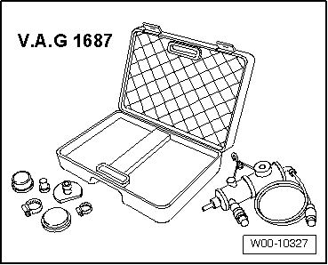
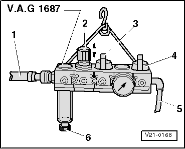
–  Connect compressed air hose -1- (compressed air supply) to charge air system tester -V.A.G 1687-.
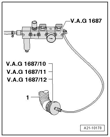
  Note
If there is water in inspection glass, drain via drain screw -6-.
–  Open valve -3-.
–  Set pressure to 0.5 bar at pressure control valve -2-.
  Caution
The pressure must not exceed 0.5 bar! If the pressure is too high this can cause damage to the engine.
–  Open valve -4- and wait until test circuit is full. If necessary, regulate pressure to 0.5 bar.
–  Check charge-air system for leaks by:
t  listening
t  feeling
t  using standard leak detecting spray
t  Ultrasonic tester -V.A.G 1842-
  Note
t  Slight leaks on the intake side of turbocharger are permissible, as the intake hoses are not designed for high-pressure.
t  A small amount of air escapes through the valves and enters the engine. Therefore a holding pressure test is not possible.
t  How to use the ultrasonic tester -V.A.G 1842- → operating instructions
t  If a leak has been located, observe notes for charge air system when carrying out any repair work.
t  Depressurise test circuit by detaching coupling from adapter -1687/10- before removing adapter.
Reassembly
Installation is carried out in the reverse order; note the following:
  Note
t  Renew the seal and O-ring.
t  Hose connections and air intake pipes/hoses must be free of oil and grease when installing.
t  Secure hose connections with hose clips corresponding to the series equipment → Electronic parts catalogue.
–  Installing inlet connection and pulsation damper → Chapter.
–  Installing intake hoses with screw-type clips → Chapter.
  V21-0168

Fuel preparation system Diesel injection > < Removing and installing charge pressure sender