
Golf Mk6
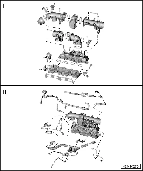
| Assembly overview - intake manifold |
 Note
Note
|
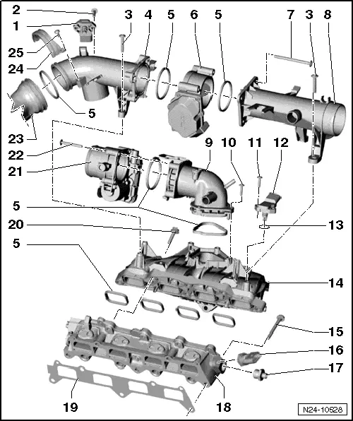
| 1 - | Intake air temperature sender 3 -G520- with intake manifold pressure sender 3 -G583- |
| 2 - | 5 Nm |
| 3 - | 7 Nm |
| q | Self-tapping bolt. |
| q | The securing bolt may only be tightened using a power-operated screwdriver if the screwdriver speed is max. 500 rpm and a max. tightening torque of 7 Nm is set. |
| 4 - | Intake connecting pipe |
| 5 - | Seal |
| q | Renew. |
| q | Before installing, lightly coat seal with clean engine oil. |
| 6 - | Regulating flap control unit -J808- |
| q | Removing and installing → Chapter |
Note| Regulating flap control units with plastic housing need not be adapted to the engine control unit -J623-. |
| q | If renewed, erase learnt values and adapt engine control unit -J623- → Vehicle diagnostic tester„Guided functions“. |
| 7 - | 7 Nm |
| q | Self-tapping bolt. |
| q | The securing bolt may only be tightened using a power-operated screwdriver if the screwdriver speed is max. 500 rpm and a max. tightening torque of 7 Nm is set. |
| 8 - | Intake connecting pipe |
| 9 - | Intake manifold connection |
| 10 - | 7 Nm |
| q | Self-tapping bolt. |
| q | The securing bolt may only be tightened using a power-operated screwdriver if the screwdriver speed is max. 500 rpm and a max. tightening torque of 7 Nm is set. |
| 11 - | 5 Nm |
| 12 - | Intake manifold pressure sender -G71- |
| 13 - | O-ring |
| q | Renew. |
| 14 - | Intake manifold |
Note| t | If the intake manifold was removed, you must check that all hoses are securely connected on the intake manifold after installation. |
| t | Pull hoses with fastener to make sure they are securely connected. |
| q | To remove: removing and installing regulating flap control unit -J808- and throttle valve module -J338- → Chapter. |
| 15 - | 20 Nm |
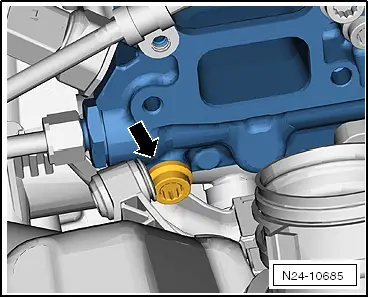
| 16 - | Fuel pressure sender -G247-, 22 Nm |
| q | Checking fuel pressure in high-pressure section → Chapter. |
| 17 - | 80 Nm |
| 18 - | Intake manifold lower part |
| q | To remove and install: using "bracket for bits 5/16""" -V.A.G 1766/2- and Bit -3320/2- → Fig. |
| q | To remove, removing and installing regulating flap control unit -J808-, throttle valve module -J338- and intake manifold → Chapter. |
| 19 - | Seal |
| q | Renew. |
| q | Note installation position. |
| 20 - | 20 Nm |
| 21 - | Throttle valve module -J338- |
| q | Removing and installing → Chapter |
| q | Clean → Chapter. |
| q | If renewed, erase learnt values and adapt engine control unit -J623- → Vehicle diagnostic tester„Guided functions“. |
| 22 - | 7 Nm |
| 23 - | Pressure pipe |
| q | From turbocharger |
| 24 - | Retaining clip |
| 25 - | 7 Nm |
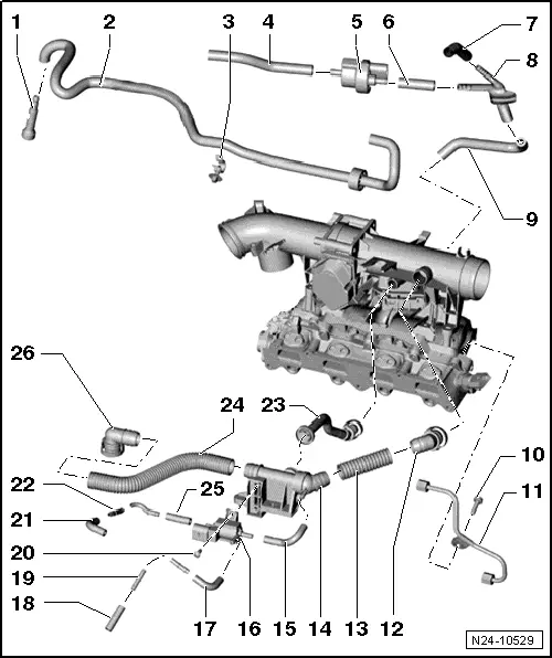
| 1 - | Connection |
| q | For fuel supply. |
| 2 - | Fuel hose |
| q | For fuel supply. |
| q | Low-pressure. |
| q | To high-pressure pump. |
| 3 - | Retaining clamp |
| 4 - | Connecting hose |
| q | To activated charcoal filter solenoid valve 1 -N80- |
| 5 - | Activated charcoal filter solenoid valve 1 -N80- |
| 6 - | Connecting hose |
| 7 - | To pressure pipe. |
| 8 - | Connecting pipe |
| 9 - | Connecting hose |
| q | To intake manifold connection. |
| 10 - | 8 Nm |
| 11 - | Fuel pipe |
| q | High-pressure. |
| q | Specified torque for union nuts: 18 Nm. |
| 12 - | Connection |
| q | To intake connecting pipe. |
| 13 - | Connecting hose |
| 14 - | Non-return valve |
| q | For crankcase ventilation. |
| q | Specified torque: 10 Nm |
| 15 - | Connecting hose |
| 16 - | Charge pressure control solenoid valve -N75- |
| 17 - | Connecting hose |
| 18 - | Connecting hose |
| q | To turbocharger. |
| 19 - | Connection |
| 20 - | 5 Nm |
| 21 - | Connecting hose |
| q | To turbocharger. |
| 22 - | Connection |
| 23 - | Connection |
| q | For crankcase ventilation. |
| 24 - | Connecting hose |
| q | For crankcase ventilation. |
| 25 - | Connecting hose |
| q | To charge pressure control solenoid valve -N75-. |
| 26 - | Connection |
| q | For crankcase ventilation. |
| q | Connected to valve timing housing. |
| q | Specified torque: 10 Nm |