
Golf Mk6
| Assembly overview - parts of cooling system - thermostat side |
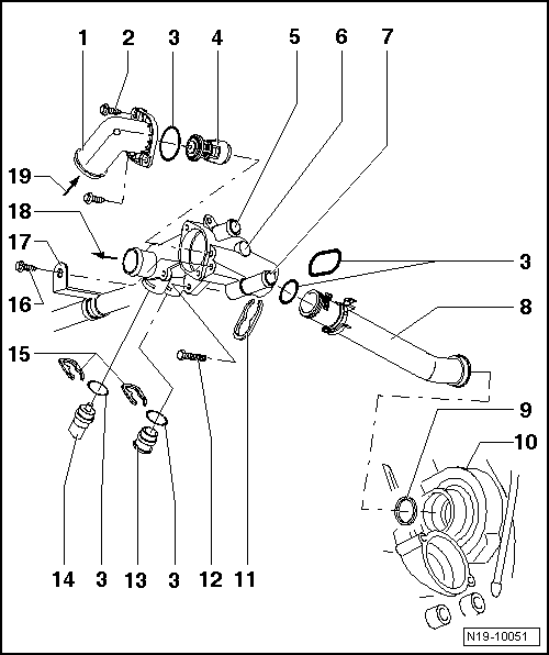
| 1 - | Connection |
| 2 - | Self-tapping bolt, 7 Nm |
| 3 - | O-ring |
| q | Renew. |
| 4 - | Thermostat |
| q | Checking: heat thermostat in water. |
| q | Opening begins at approx. 84 °C. |
| q | Fully open: at approx. 98 °C. |
| q | Opening lift :min. 7 mm |
| 5 - | To heat exchanger |
| q | Coolant hose schematic diagram → Chapter. |
| 6 - | Thermostat housing |
| 7 - | From heat exchanger |
| q | Coolant hose schematic diagram → Chapter. |
| 8 - | Coolant pipe |
| 9 - | Seal |
| q | Renew. |
| 10 - | Coolant pump housing on cylinder block |
| 11 - | Retaining clip |
| q | Check for secure seating. |
| 12 - | 10 Nm |
| 13 - | Plug |
| q | Before removing, release pressure in cooling system if necessary. |
| 14 - | Coolant temperature sender -G62- |
| q | Release pressure in cooling system before removing. |
| Engine code BCA |
| q | To remove, first remove air filter housing → Fig.. |
| 15 - | Retaining clip |
| q | Check for secure seating. |
| 16 - | Self-tapping bolt, 7 Nm |
| 17 - | Connecting pipe |
| q | For exhaust gas recirculation. |
| 18 - | To bottom of radiator |
| q | Coolant hose schematic diagram → Chapter. |
| 19 - | From top of radiator |
| q | Coolant hose schematic diagram → Chapter. |