| –
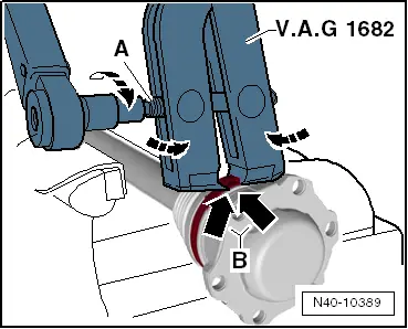
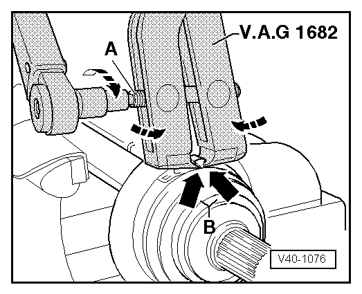
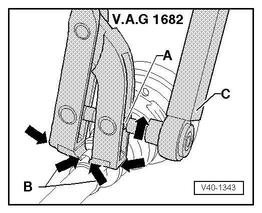
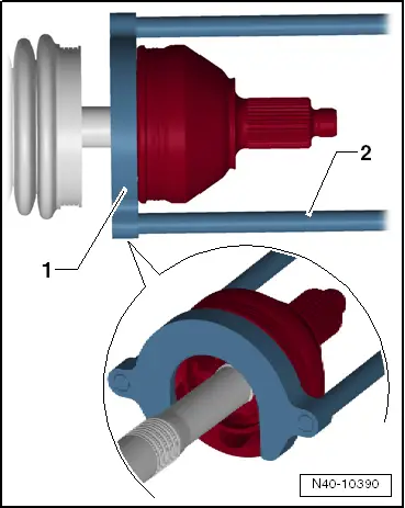
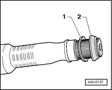
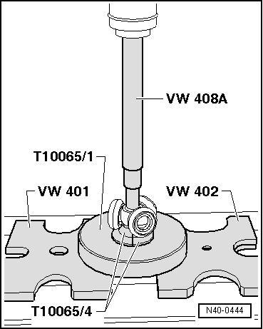
| Fit triple roller star onto shaft and press on to stop. |
| –
| Ensure that pressure does not exceed 3.0 t. |
| –
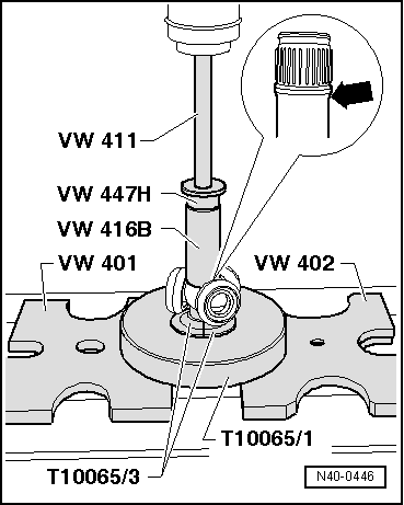
| If necessary, coat splines of drive shaft and triple roller star with lubricant paste G 052 142 A2. |
| –
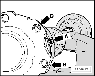
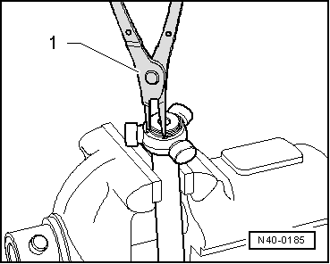
| Insert retaining ring, ensuring that it is seated correctly. |
| As of 08.2004, a different grease is used in the triple roller joints. This grease cannot be mixed with the previous one. The triple roller joint must therefore be cleaned before greasing during repair work. |
| –
| Press 70 grammes of drive shaft grease from repair set into triple roller joint. |
| –
| Slide joint body over rollers and hold. |
| –
| Press 60 grammes of drive shaft grease from repair kit into rear of triple roller joint. |
| Fitting triple roller star |
| Drive shaft (cylindrical version) |
|
|

|


 Note
Note