Golf Mk6
| Assembly overview: drive shaft with VL107 constant velocity joint (bolt-on) |
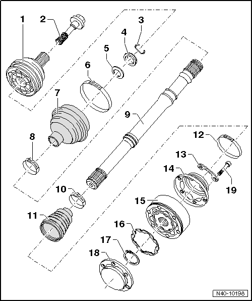
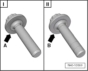
| 1 - | Outer constant velocity joint |
| q | Renew only as complete unit |
| q | Removing → Fig.. |
| q | Installing: drive onto shaft to stop using a plastic mallet |
| q | Checking → Chapter |
| 2 - | Bolt |
| q | Various versions |
| q | Allocation → Electronic parts catalogue „ETKA“ |
 WARNING
|
| q | Always renew after removing. |
| 3 - | Retaining ring |
| q | Always renew after removing. |
| q | Insert in groove in shaft |
| 4 - | Thrust washer |
| q | Installation position → Fig.. |
| 5 - | Dished spring |
| q | Installation position → Fig.. |
| 6 - | Clamp |
| q | Always renew after removing. |
| q | Tightening → Fig. |
| 7 - | Boot |
| q | Check for splits and chafing |
| q | Material: Hytrel (polyester elastomer) |
| 8 - | Clamp |
| q | Always renew after removing. |
| q | Tightening → Fig. |
| 9 - | Drive shaft |
| 10 - | Clamp |
| q | Always renew after removing. |
| q | Tightening → Fig. |
| 11 - | Boot for constant velocity joint |
| q | Material: Hytrel (polyester elastomer) |
| q | Without breather hole |
| q | Check for splits and chafing |
| q | Drive off constant velocity joint with a drift |
| q | Coat sealing surface of constant velocity joint with -D 454 300 A2- before installing. |
| 12 - | Clamp |
| q | Always renew after removing. |
| 13 - | Locking plate |
| 14 - | Cap |
| q | Drive off carefully with drift |
| q | Coat sealing surface of constant velocity joint with -D 454 300 A2- before installing. |
| q | Adhesive surface must be free of oil and grease! |
| 15 - | Inner constant velocity joint |
| q | Renew only as complete unit |
| q | Pressing off → Fig. |
| q | Pressing on → Fig. |
| q | Checking → Chapter |
| 16 - | Seal |
| q | Adhesive surface on constant velocity joint must be free of oil and grease! |
| 17 - | Retaining ring |
| q | Remove and install with circlip pliers -VW 161 A- |
| 18 - | Cover |
| q | Always renew after removing. |
| q | Always renew |
| q | Pressing off → Fig. |
| 19 - | Multi-point socket head bolt |
| q | M10 x 52 |
| q | Initially tighten diagonally to 10 Nm and then tighten diagonally to specified torque |
| q | 70 Nm |
| q | Always renew bolts after removing |