volkswagen Workshop Repair Guides

Volkswagen Workshop Service and Repair Manuals

Checking front parking aid sender > < Front parking aid senders
Removing and installing front parking aid senders
  Note
t  
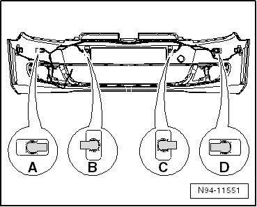
The following illustrations show the removal and installation of the front left parking aid sender.
t  The removal and installation of the other parking aid senders are carried out in the same way.
t  Both exterior front left parking aid sender -G255- and front right parking aid sender -G252- can also be removed through installation aperture of fog light. Depending on equipment, remove either front cover in bumper cover or fog light → Chapter.
Removing:
–  Switch off ignition and all electrical consumers and remove ignition key.
–  Remove front bumper cover → General body repairs, exterior; Rep. gr.63.
  Caution
t  
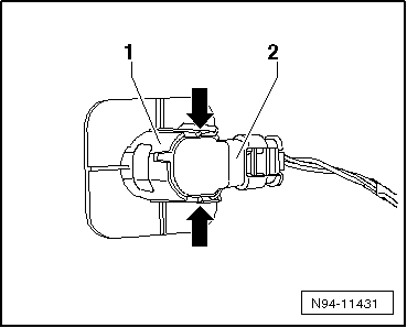
The order for removing the senders must be adhered to under all circumstances.
t  The sender may otherwise be damaged. Fractures may occur if too much pressure is applied to the sender, and this may cause the sender to fail.
t  
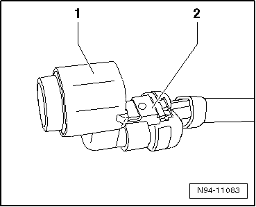
First remove sender from bracket and then disconnect sender connector.
   
–  Push fasteners -arrows- on sender bracket -1- outwards.
–  Pull sender -2- with connected wiring backwards out of sender bracket.
  Note
t  When removing the sender, ensure the isolation ring (black silicone ring) remains on the sender head and does not remain stuck in the bracket or become lost.
t  Expanding the isolation ring must be avoided under all circumstances.
  N94-11431
–  Release and disconnect connector -2- and remove sender -1-.
Installing:
Install in the reverse order of removal. When doing this, note the following:
  Caution
t  Expanding the isolation ring must be avoided under all circumstances.
t  Function problems could occur if an incorrect or damaged isolation ring is used.
t  Renew damaged isolation rings and always ensure that the correct isolation ring is fitted.
  Note
As the front parking aid sender and the park assist steering senders have sender heads of different lengths, isolation rings of different heights are also installed.
  N94-11083
–  Check whether the correct isolation ring is installed on the sender head.
  N94-11088
Type of senderIsolation ring height dimension -B-
Front parking aid senders5.7 mm
Park assist steering senders9.05 mm

–  If necessary, renew the sender's isolation ring -1-.
–  Assign senders to correct fitting location in bumper cover.
  Note
t  Senders are available in different forms and must be assigned to respective fitting location in bumper cover.
t  When installing senders, note position of electrical connections of senders.
   
Assignment of parking aid sender on inside of rear bumper cover:
A - FL - left outer
B - FLC - left centre
C - FRC - right centre
D - FR - right outer
  Note
t  When mounting the sender, make sure that the isolation ring is correctly mounted on the sender head and does not ride or roll up on insertion into the sender retainer.
t  Both locking lugs of sender bracket must audibly engage when installing the sender.
  N94-11551
–  After installing the sender, check that the sender is correctly seated in the bracket. Visible on the outer side of the bumper, dimension -a- of the ring gap between the sender head and bumper cover must be even all around.
  N94-10605

Checking front parking aid sender > < Front parking aid senders