volkswagen Workshop Repair Guides

Volkswagen Workshop Service and Repair Manuals

Removing and installing parts of charge air cooling system > < Charge air system with turbocharger
4-Cyl. diesel engine, Mech.
Charge air system with turbocharger
Removing and installing turbocharger with attachments

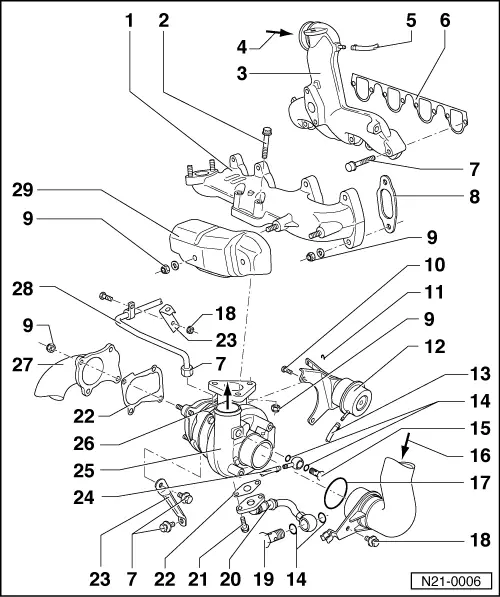
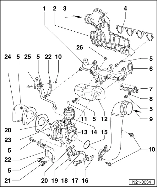
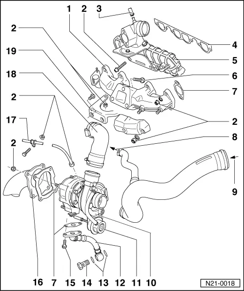
Observe rules for cleanliness .

Engine codes 1Z, AHU

Engine code AFN

Engine code AAZ

Turbocharger hose connections => Page 21-17 .

Notes:

  • ◆ All hose connections are secured with clips.
  • ◆ Charge air system must be free of leaks.
  • ◆ Renew self-locking nuts.
  • ◆ Before screwing on oil supply pipe fill turbocharger at connection with engine oil.
 
N21-0006

Engine code 1Z, AHU

  • Exhaust manifold
  • 35 Nm
    • ◆ Renew
    • ◆ Coat threads and bolt head seating surface with G000500
  • Intake manifold
  • From charge air cooler
  • Hose
    • ◆ Black
    • ◆ To diesel direct injection system control unit (J248)
  • Gasket
    • ◆ Renew
    • ◆ Coating (beading) towards intake manifold
  • 25 Nm
 
N21-0006
  • Gasket
    • ◆ Note installation position
  • 25 Nm
  • 10 Nm
    • ◆ Install with D6
  • Circlip
  • Pressure unit
    • ◆ For charge pressure regulating valve
    • ◆ Checking
    • ◆ Removing and installing
      => Page 21-35
  • Hose
    • ◆ Blue
    • ◆ To charge pressure control solenoid valve (N75) => Page 21-17 , turbocharger hose connections
  • Seal
    • ◆ Renew
 
N21-0006
  • Banjo bolt, 15 Nm
  • From air cleaner
  • O-ring
    • ◆ Renew if damaged
  • 10 Nm
  • Banjo bolt, 30 Nm
  • Oil return pipe
    • ◆ To cylinder block
  • 30 Nm
  • Gasket
    • ◆ Renew
  • Retainer
  • Hose
    • ◆ rot
    • ◆ To charge pressure control solenoid valve (N75) => Page 21-17 , turbocharger hose connections
 
N21-0006
  • Turbocharger
    • ◆ Removing and installing
      => Page 21-20
    • ◆ Checking boost pressure
      => Page 21-28
  • To charge air cooler
  • Front exhaust pipe
  • Oil supply pipe
    • ◆ From oil filter bracket
      => Page 17-3 , item 8
    • ◆ Before installing, fill turbocharger with engine oil via oil supply pipe connection
  • Heat shield
 
N21-0034

Engine code AFN

  • Exhaust manifold
  • Intake manifold
    • ◆ With exhaust gas recirculation valve
  • From charge air cooler
  • Gasket
    • ◆ Renew
    • ◆ Coating (beading) towards intake manifold
  • 25 Nm
  • Gasket
    • ◆ Note installation position
  • Retainer
    • ◆ For heat shield item 12
  • Washer
  • From air cleaner
  • 10 Nm
 
N21-0034
  • Hose
    • ◆ To charge pressure control solenoid valve (N75) => Page 21-17 , turbocharger hose connections
  • Heat shield
    • ◆ Engage in bracket item 7
  • Turbocharger
    • ◆ Removing and installing
      => Page 21-20
    • ◆ Checking charge pressure

=> Repair group 23; Servicing diesel direct injection system; Checking charge pressure system

  • Pressure unit
    • ◆ For charge pressure control
    • ◆ Integral part of turbocharger cannot be replaced
  • O-ring
    • ◆ Renew if damaged
  • Seal
    • ◆ Renew
 
N21-0034
  • Banjo bolt, 30 Nm
  • Oil return pipe
    • ◆ To cylinder block
  • 30 Nm
  • Gasket
    • ◆ Renew
  • 30 Nm
  • Retainer
  • To charge air cooler
  • Front exhaust pipe
  • Oil supply pipe
    • ◆ From oil filter bracket
      => Page 17-3 , item 8
    • ◆ Before installing, fill turbocharger with engine oil via oil supply pipe connection
  • 25 Nm
    • ◆ Renew
    • ◆ Coat threads and bolt head seating surface with G 000 500
 
N21-0018

Engine code AAZ

Note:

  • ◆ The charge pressure control is switched off during partial throttle operations by exhaust gas recirculation partial throttle switch (F166) and the exhaust gas recirculation two-way valve (N161).
  • ◆ Checking and adjusting partial throttle switch
  • ◆ Checking two-way valve
    => Page 26-28
  • Exhaust manifold
  • 25 Nm
  • Hose
    • ◆ To injection pump
  • Gasket
    • ◆ Renew
    • ◆ Coating (beading) towards intake manifold
 
N21-0018
  • Intake manifold
  • 45 Nm
    • ◆ Renew
    • ◆ Coat threads and bolt head seating surface with G000500
  • Gasket
    • ◆ Renew
    • ◆ Note installation position
  • To crankcase breather
  • From air cleaner
  • Turbocharger
    • ◆ Removing and installing
      => Page 21-20
    • ◆ Checking boost pressure
      => Page 21-28
  • Charge pressure regulating valve
    • ◆ Integral part of turbocharger cannot be replaced
    • ◆ Hose/pipe connections
      => Page 21-17
 
N21-0018
  • Oil return pipe
    • ◆ To cylinder block
  • Sealing ring
    • ◆ Renew
  • Banjo bolt, 30 Nm
  • 30 Nm
  • Front exhaust pipe
  • Oil supply pipe
    • ◆ From oil filter bracket
      => Page 17-3 , item 8
    • ◆ Before installing, fill turbocharger with engine oil via oil supply pipe connection
  • Air hose
  • Retainer
    • ◆ Between exhaust pipe and exhaust manifold

Removing and installing parts of charge air cooling system > < Charge air system with turbocharger