volkswagen Workshop Repair Guides

Volkswagen Workshop Service and Repair Manuals

4-cyl. fuel injection engine (cross-flow cylinder head) > < Checking fuel tank breather
4-Cyl. fuel injection engine (4-valve), Mechanics
Removing and installing parts of exhaust system

Notes:

  • ◆ After working on the exhaust system ensure that the system is not under stress, and that it has sufficient clearance from the bodywork. If necessary, loosen clamps and align silencer so that sufficient clearance is maintained to the bodywork and the support rings are evenly loaded.
  • ◆ Renew self-locking nuts.
 
N26-0056

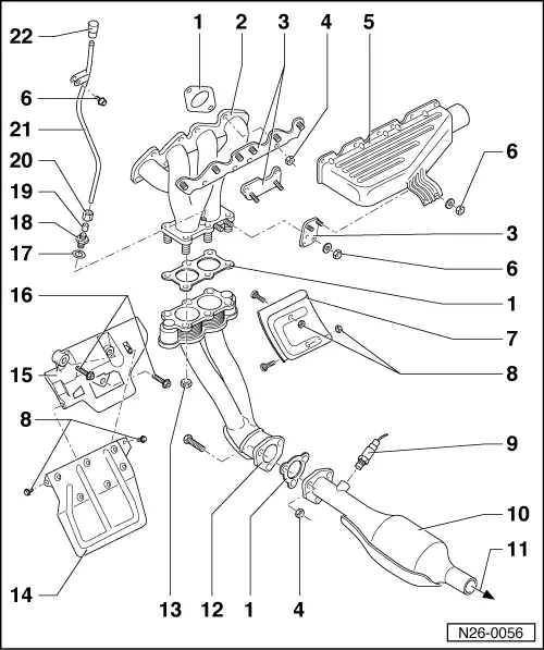
Exhaust manifold, front exhaust pipe and catalyst with attachments

  • Gasket
    • ◆ Renew
  • Exhaust manifold
  • Bracket
  • 20 Nm
  • Warm air collector plate
  • 20 Nm
  • Heat shield
    • ◆ Only left hand drive vehicles
  • 10 Nm
  • Lambda probe, 50 Nm
    • ◆ Grease only the threads with "G5"; "G5" must not get into the slots on the probe body
    • ◆ Remove and install with 3337
    • ◆ Checking:
 
N26-0056

=> Repair group 24; Digifant injection and ignition system; Checking Lambda probe and Lambda control

  • Catalyst
  • To front silencer
    • ◆  , Pos. 4
  • Front exhaust pipe
    • ◆ Left hand drive vehicles as illustrated
    • ◆ Right hand drive vehicles with heat protection shielding
    • ◆ To remove loosen sub-frame, support on right with engine and gearbox jack V.A.G 1383A and remove bolts on right. Lower sub-frame on right by approx. 10 mm. Sub-frame to body bolts tightening torque:

=> Running gear; Repair group 40; Servicing front suspension (Plus running gear); Removing and installing sub-frame, anti roll bar, wishbone (Plus running gear)

 
N26-0056
  • 40 Nm
    • ◆ Tightening sequence => Fig. 1
  • Heat shield
  • Console
  • 35 Nm
  • Sealing ring
    • ◆ Renew
  • 35 Nm
  • Olive
  • 30 Nm
  • CO take-off pipe
  • Cap
 
N26-0008

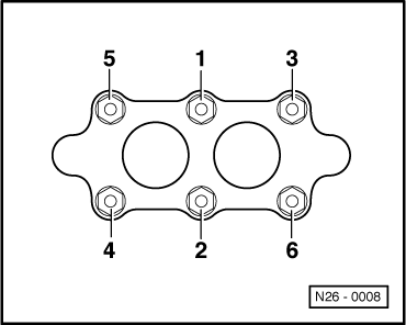
→ Fig. 1     Tightening sequence exhaust pipe to exhaust manifold

 
N26-0057

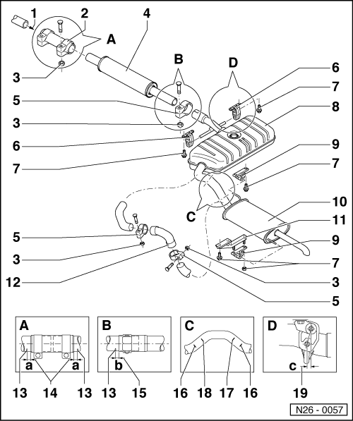
Silencer with mountings

Note:

Align the exhaust system longitudinally so that the dimensions -14 -, -15 -, and -19 - are maintained.

  • From catalyst
  • Double clamp
  • 40 Nm
  • Front silencer
  • Clamp
  • Mounting
    • ◆ Note fitting position
  • 25 Nm
  • Centre silencer1)
  • Mounting
 
N26-0057
  • Rear silencer1)
  • Console
  • Repair connecting pipe
  • Marking
    • ◆ Three times on circumference
  • Dimension-a- = ca. 5 mm
  • Dimension -b- = approx. 5 mm
  • Marking
    • ◆ For clamp
    • ◆ Three times on circumference
    • ◆ Distance clamp/marking => Pos. 15
  • Separating point
    • ◆ For repair cases1)
    • ◆ When replacing the centre silencer Pos. 8
    • ◆ Marked by three impressions on circumference of connecting pipe
 
N26-0057
  • Separating point
    • ◆ For repair cases1)
    • ◆ When replacing the rear silencer
      Pos. 10
    • ◆ Marked by three impressions on circumference of connecting pipe
  • Pre-tension
    • ◆ c = 6...10 mm
    • ◆ With exhaust system cold

1)     As standard central and rear silencer are installed as one component. In repair cases the central and rear silencer are supplied individually and a repair connecting pipe item 12 with two clamps supplied as a joint. Cut through connecting pipe at separating point -17 - or -18 - at right angles with a body saw e.g. V.A.G 1523.

4-cyl. fuel injection engine (cross-flow cylinder head) > < Checking fuel tank breather