volkswagen Workshop Repair Guides

Volkswagen Workshop Service and Repair Manuals

Servicing the activated charcoal filter system > < Removing and installing fuel delivery unit
4-cyl. fuel injection engine (cross-flow cylinder head)
Removing and installing parts of fuel supply system
Checking fuel pump

Special tools, testers and auxiliary items

  • ◆ Remote control V.A.G 1348/3A with adapter cable V.A.G 1348/3-2
  • ◆ Diode test lamp V.A.G 1527
  • ◆ Adapter set V.A.G 1594
  • ◆ Union nut spanner 3217
  • ◆ Pressure tester V.A.G 1318
  • ◆ Adapter 1318/1
  • ◆ Adapter 1318/10
  • ◆ Adapter 1318/11
  • ◆ Measuring container

Test conditions

  • ● Battery voltage OK.
  • ● Fuse No. 18 OK.

Test sequence

 
N20-0009
  • ‒ Switch ignition on.

Fuel pump must be heard to run briefly.

If the fuel pump does not run:

  • ‒ Switch off ignition.
  • ‒ → Pull the fuel pump relay (J17) out of relay plate (relay position 12).

Notes:

  • ◆ If tools are necessary to pull relays or control units out of the relay plate, first disconnect battery earth strap.
  • ◆ Before disconnecting battery earth strap obtain code for radios with anti-theft coding.
 
N20-0009
  • ‒ → Connect remote control V.A.G 1348/3A with adapter cable V.A.G 1348/3-2 to contact 4 and battery positive (+).
  • ‒ Operate remote control.

Fuel pump runs:

  • ‒ Check activation of fuel pump relay:

=> Repair group 01; Self-diagnosis; final control diagnosis

Fuel pump does not run:

  • ‒ Remove cover in luggage boot floor.
 
V20-1043
  • ‒ Pull connector off fuel tank flange.
  • ‒ → Connect diode test lamp V.A.G 1527 with aux. cables from V.A.G 1594 to the outer contacts of the connector.
  • ‒ Operate remote control.
         LED must light up

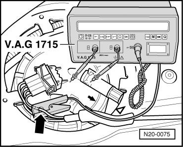
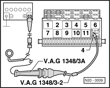
LED does not light up:

  • ‒ Locate and eliminate open circuit using current flow diagram

LED lights up (voltage supply OK.):

  • ‒ Unscrew union nut with 3217.
  • ‒ Check that the electrical wires between flange and fuel pump are connected.

If not open circuit can be found:

  • ‒ Renew fuel delivery unit.

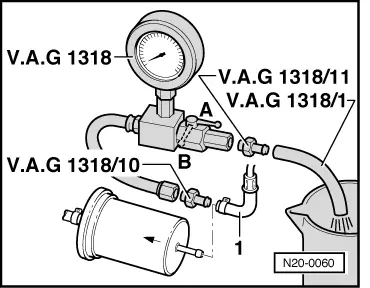
Checking delivery rate

  • ● Voltage supply OK.
  • ● Remote control V.A.G 1348/3A connected.

Test sequence

  • ‒ Remove filler cap from fuel tank filler neck.
Warning!
Fuel supply lines are under pressure! Before removing from hose connection wrap a cloth around the connection. Then release pressure by carefully pulling hose off connection.

 
V20-1015
  • ‒ Pull fuel supply pipe -1- off fuel manifold.
  • ‒ → Connect pressure gauge V.A.G 1318 with adapter 1318/10 to the fuel supply pipe -1- .
  • ‒ Push the hose V.A.G 1318/1 onto the adapter V.A.G 1318/11 on the pressure gauge and hold hose in a measuring container.
  • ‒ Open the pressure gauge shut-off tap. The lever then points in the direction of flow -A-.
  • ‒ Operate remote control V.A.G 1348/3A and slowly close cut-off tap, until pressure gauge shows
         3 bar.
    From this point on do not move position of cut-off tap.
  • ‒ Empty the measuring container.
  • ‒ Connect multimeter to vehicle battery to measure voltage using auxiliary cables from V.A.G 1594.
  • ‒ Operate remote control for
         30 seconds.
 
V20-0934
  • ‒ → Compare the quantity of fuel delivered with specification.

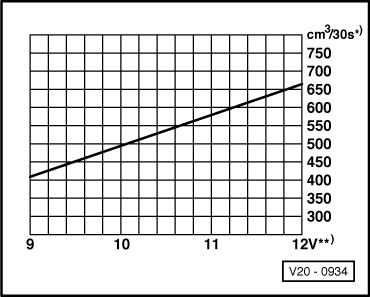
     *)     Minimum delivery cm3/30 seconds

     **)     Voltage at fuel pump with engine stopped and pump running (approx. 2 volts less than battery voltage).

If the minimum delivery rate is not attained:

  • ‒ Check the fuel pipes for possible restrictions (kinks) or blockages.
 
N20-0060
  • ‒ → Pull the supply hose -1- off inlet to fuel filter.
  • ‒ Connect the pressure gauge V.A.G 1318 to hose with adapter 1318/10.
  • ‒ Repeat delivery rate check.

If the minimum delivery rate is now attained:

  • ‒ Replace the fuel filter.

If the minimum delivery rate is again not attained:

  • ‒ Remove fuel delivery unit ( ) and check the strainer for soiling.

Only when up to now no fault has been detected:

  • ‒ Replace the fuel delivery unit.

If the delivery rate has been attained but nevertheless you suspect a fuel supply system fault (e.g. intermittent failure of fuel supply system):

  • ‒ Check the current draw of the fuel pump as follows:
  • ‒ Reconnect all disconnected fuel pipes.
 
N20-0075
  • ‒ → Connect the multimeter V.A.G 1715 using the current clamp to the red/white wire from wiring loom.
  • ‒ Start the engine and run at idling speed.
  • ‒ Measure the current draw of the fuel pump.
         Specification: max. 8 amps.

Note:

If the fuel system malfunction is intermittent, you can perform the check during a test drive with the help of a 2nd person.

If the current draw is exceeded:

  • ‒ Replace the fuel delivery unit.

Checking fuel pump non-return valve

  • ● Remote control V.A.G 1348/3A connected
  • ● Pressure gauge V.A.G 1318 connected to the fuel supply pipe at fuel manifold

Note:

 
V20-0780

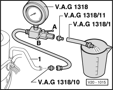
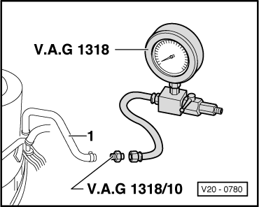
With this check the fuel supply pipe connections from the fuel delivery unit to the point at which the pressure gauge V.A.G 1318 is connected will be checked for leaks at the same time.

  • ‒ → Close pressure gauge cut-off tap (lever at right angles to throughflow direction).
  • ‒ Operate remote control at short intervals, until a pressure of
         approx. 3 bar
    has built-up.
  • ‒ If pressure builds up too high, lower excess pressure by carefully opening the cut-off tap.
Warning!
Danger of spray when opening the shut-offtap, hold container over the free connection of the pressure gauge.
  • ‒ Observe pressure drop. After 10 minutes the pressure must not drop
         below 2.0 bar,
    if necessary check line connections for leaks and/or renew fuel delivery unit
    , Removing and installing fuel delivery unit

Servicing the activated charcoal filter system > < Removing and installing fuel delivery unit