volkswagen Workshop Repair Guides

Volkswagen Workshop Service and Repair Manuals

Exhaust gas recirculation system > < Checking fuel tank breather
4-Cyl. Injection Engine, Mechanic
Removing and installing parts of exhaust system

Exhaust manifold, front exhaust pipe and catalyst with attachments for vehicles ▸ 07.95

Exhaust manifold, front exhaust pipe and catalyst with attachments for vehicles 08.95 ▸ => Page 26-5

Silencer with mountings => Page 26-9

Exhaust gas recirculation system (Vehicles ▸07.95 only) => Page 26-13

Checking secondary air system for vehicles ▸ 07.95 => Page 26-19

Checking secondary air system for vehicles 08.95 ▸ => Page 26-28

Notes:

  • ◆ After working on the exhaust system ensure that the system is not under stress, and that it has sufficient clearance from the bodywork. If necessary, loosen double and single clamps and align silencer and exhaust pipe so that sufficient clearance is maintained to the bodywork and the support rings are evenly loaded.
  • ◆ Renew self-locking nuts.
 
N26-0111

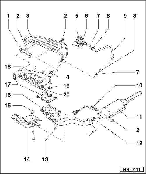
Exhaust manifold, front exhaust pipe and catalyst with attachments

Vehicles ▸07.95

  • Bracket
    • ◆ For warm air collector plate
  • 25 Nm
  • Warm air collector plate
  • 35 Nm
  • Exhaust gas recirculation valve
  • Exhaust gas recirculation temperature sensor
  • Olive
  • 30 Nm
  • Exhaust gas recirculation pipe
 
N26-0111
  • Lambda probe, 50 Nm
    • ◆ Grease only the threads with "G5"; "G5" must not get into the slots on the probe body
    • ◆ Remove and install with 3337
    • ◆ Checking:

=> Repair group 24; servicing injection and ignition system

  • Catalyst
  • Sealing ring
    • ◆ Renew
  • 40 Nm
    • ◆ Tightening sequence => Fig. 1
  • Heat shield
  • 10 Nm
 
N26-0111
  • Front exhaust pipe
  • Gasket
    • ◆ Renew
  • Exhaust manifold
  • 35 Nm
    • ◆ Connecting union for pipe , item 15
  • Secondary air inlet
 
N26-0108

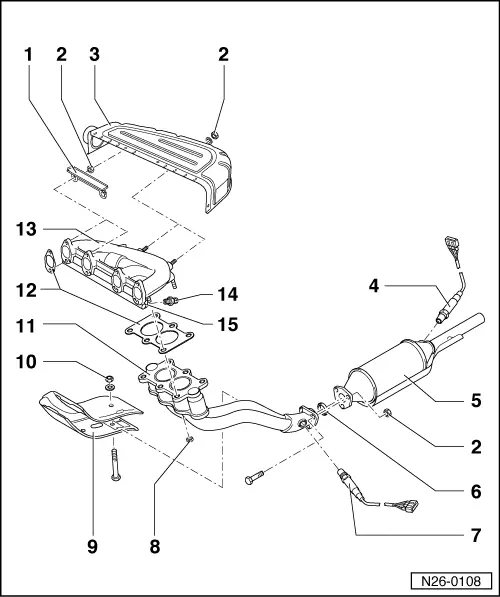
Exhaust manifold, front exhaust pipe and catalyst with attachments

Vehicles08.95 ▸

  • Bracket
    • ◆ For warm air collector plate
  • 25 Nm
  • Warm air collector plate
  • Lambda probe after catalyst (G108)*, 50 Nm
    • ◆ Fitting location: catalyst
    • ◆ Grease only the threads with "G5"; "G5" must not get into the slots on the probe body
    • ◆ Remove and install with 3337
    • ◆ Checking:

=> Repair group 24; servicing injection and ignition system

 
N26-0108
  • Catalyst
  • Sealing ring
    • ◆ Renew
  • Lambda probe before catalyst (G39)*, 50 Nm
    • ◆ Fitting location: catalyst
    • ◆ Grease only the threads with "G5"; "G5" must not get into the slots on the probe body
    • ◆ Remove and install with 3337
    • ◆ Checking:

=> Repair group 24; servicing injection and ignition system

  • 40 Nm
    • ◆ Tightening sequence => Fig. 1
  • Heat shield
  • 10 Nm
  • Front exhaust pipe
 
N26-0108
  • Gasket
    • ◆ Renew
  • Exhaust manifold
  • 35 Nm
    • ◆ Connecting union for pipe , item 15
  • Secondary air inlet
 
N26-0008

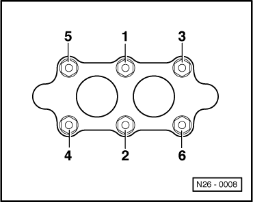
→ Fig. 1     Tightening sequence exhaust pipe to exhaust manifold

 
N26-0014

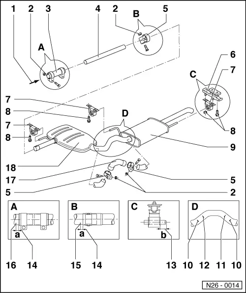
Silencer with mountings

Note:

Align the exhaust system longitudinally so that the dimensions -a-, -b- and -c- are maintained.

  • From catalyst
  • 40 Nm
  • Double clamp
  • Intermediate pipe
  • Clamp
  • Console
  • Mounting
  • 25 Nm
  • Rear silencer
 
N26-0014
  • Marking
    • ◆ For clamp
    • ◆ Three times on circumference
    • ◆ Distance clamp/marking => Item 14
  • Separating point
    • ◆ For repair cases
    • ◆ When replacing central silencer
    • ◆ Marked by three impressions on circumference of connecting pipe
    • ◆ Central and rear silencer are installed as one part as standard. In repair cases the central and rear silencer are supplied individually and a repair connecting pipe with two clamps supplied as joint.
    • ◆ Cut through connecting pipe with body saw e.g. V.A.G 1523 at right angles at the separating point.
 
N26-0014
  • Separating point
    • ◆ For repair cases
    • ◆ When replacing rear silencer
    • ◆ Marked by three impressions on circumference of connecting pipe
    • ◆ Central and rear silencer are installed as one part as standard. In repair cases the central and rear silencer are supplied individually and a repair connecting pipe with two clamps supplied as joint.
    • ◆ Cut through connecting pipe with body saw e.g. V.A.G 1523 at right angles at the separating point.
  • Dimension -b- = approx. 10 mm
  • Dimension-a- = ca. 5 mm
 
N26-0014
  • Marking
    • ◆ Three times on circumference
  • Marking
    • ◆ Three times on circumference
    • ◆ S = Manual gearbox
      A = Auto. gearbox
  • Repair connecting pipe
  • Centre silencer

Exhaust gas recirculation system > < Checking fuel tank breather