volkswagen Workshop Repair Guides

Volkswagen Workshop Service and Repair Manuals

Hose connection diagram for charge pressure control, engine code AFN > < Checking injection adjuster control range
Diesel direct injection and glow plug system
Servicing Diesel direct injection system
Checking charge pressure control

Special tools, testers, measuring instruments and auxiliary items required

  • ◆ Fault reader V.A.G 1551 or vehicle system tester V.A.G 1552 with cable V.A.G 1551/3
  • ◆ Turbocharger tester V.A.G 1397 A
  • ◆ Test box V.A.G 1598/18
  • ◆ Hand multimeter V.A.G 1526 or multimeter V.A.G 1715
  • ◆ Adapter set V.A.G 1594
  • ◆ Current flow diagram

Engine code 1Z, AHU

Engine code AFN

To enable the charge pressure control to be checked it is essential that the charge pressure is known without charge pressure control (limiting), first

=> 4-Cyl. Diesel engine, Mechanics; Repair group 21; Check exhaust turbocharger

Test sequence

  • ‒ The charge pressure is measured with the fault reader V.A.G 1551 during a test drive.

Note:

When the charge pressure is measured during a test drive, a second person is required, for reasons of safety, to operate the fault reader.

  • ‒ Connector connected on boost pressure limitation solenoid valve -N75.
  • ‒ Connect fault reader V.A.G 1551 and select engine electronics control unit (address word 01); selection is carried out with engine idling.
 
→ Indicated on display:
Rapid data transfer     HELP
Select function XX
  • ‒ Input 08 for "Read measured value block" function and confirm with Q.
 
→ Indicated on display:
Read measured value block     HELP
Input display group number XXX
  • ‒ Press keys 0, 1 and 1 for Display Group 11 and confirm entry by pressing Q.
 
→ Indicated on display:
Read measured value block 11     "
     840 rpm     938 mbar     978 mbar     92 %    
  • ‒ Accelerate vehicle in 3rd gear from about 1500 rpm using full throttle.
  • ‒ Press PRINT key on V.A.G 1551 at about 3000 rpm.
  •  
    → Specification on V.A.G 1551: 1720...1950 mbar (in display zone 3)
    Read measured value block 11     "
         3090 rpm     1866 mbar     1917 mbar     62 %    
    • ‒ If the measured charge pressure is too low check charge pressure control valve as follows:

    Engine code AFN

    Check conditions

    • ● No leaks on intake and exhaust systems.
    • ● No faults in engine and fuel injection system, e.g. commencement of injection, injectors and compression pressure.
    • ● Engine oil temperature min. 80 °C

    Test sequence

     
    N21-0039
    • ‒ The charge pressure is measured with the turbocharger tester V.A.G 1397/A and the fault reader V.A.G 1551 during a test drive.

    Note:

    When the charge pressure is measured during a test drive, for reasons of safety, a second person is required to operate the fault reader.

    • ‒ → Pull off connecting hose running between intake manifold and diesel direct injection system control unit (J248) and using T-piece connect in turbocharger tester V.A.G 1397 A.
    • ‒ Select measuring range l.

    Notes:

    • ◆ To operate turbocharger tester see operating instructions.
    • ◆ The hoses must be connected so that there is no possibility of leaks.
    • ◆ Ensure that the pressure hose is not trapped between the bonnet and the body.
    • ‒ Connect fault reader V.A.G 1551 (V.A.G 1552) and select engine electronics control unit with the "Address word" 01. When doing this the engine must be running at idling speed.
      (Connecting fault reader and selecting engine electronics control unit => Page 01-3 .)
     
    → Indicated on display:
    Rapid data transfer     HELP
    Select function XX
    • ‒ Press keys 0 and 8 for the function "Read measured value block" and confirm entry with Q key.
     
    → Indicated on display:
    Read measured value block     HELP
    Input display group number XXX
    • ‒ Press keys 0, 1 and 1 for Display Group 11 and confirm entry by pressing Q.
     
    → Indicated on display:
    Read measured value block 11     "
         840 rpm     938 mbar     978 mbar     92 %    
  • ‒ Accelerate vehicle in 3rd gear from about 1500 rpm using full throttle.
  • ‒ Press PRINT key on V.A.G 1551 at approx. 3000 rpm and simultaneously the memory key on V.A.G 1397/A..
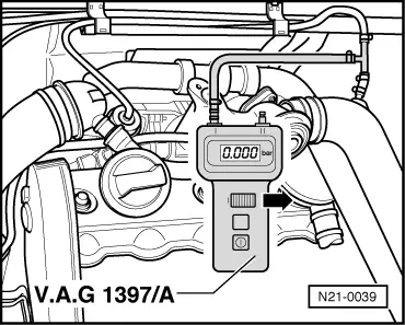
  • Specification on V.A.G 1397/A: 1.700...2.500 bar

     
    → Specification on V.A.G 1551: 1700...2500 mbar (in display zone 3)
    Read measured value block 11     "
         3090 rpm     1866 mbar     1917 mbar     62 %    

    Note:

    The charge pressure is determined with the turbocharger tester V.A.G 1397/A. The fault reader V.A.G 1551 serves as a check that the charge pressure is being recorded in the control unit.

    If the specification is not obtained:

    • ‒ Carry out final control diagnosis and activate the charge pressure control solenoid valve .
     
    → Indicated on display:
    Final control diagnosis     ⇒
    Boost pressure control solenoid valve -N75

    The solenoid valve must function and the charge pressure control pressure unit rod must move to and fro (at least 3...4 times, as long as there is vacuum in vacuum reservoir).

    • ‒ If the rod moves and the charge pressure specifications are not obtained, renew turbocharger.

    If the rod does not move:

    • ‒ Check solenoid valve for charge pressure control (N75) => Page 23-72
    • ‒ Check vacuum hoses => Page 23-77

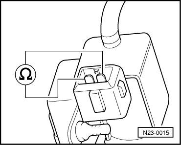
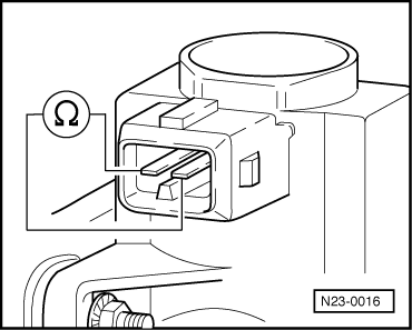
    Electrically checking charge pressure limitation solenoid valve (N75)

    • ‒ Switch off ignition.
    • ‒ Pull connector off valve =>Fitting locations overview, Page 23-4 .
    • ‒ Carry out resistance measurement between solenoid valve contacts using hand multimeter V.A.G 1526.
     
    N23-0015

    → Engine code 1Z, AHU

    Specification: 25...45 ω

     
    N23-0016

    → Engine code AFN

    Specification: 14...20 ω

    If the specification is not attained:

    • ‒ Replace boost pressure control solenoid valve (N75).

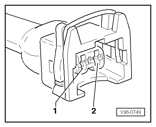
    Checking voltage supply from boost pressure control solenoid valve (N75)

    • ‒ Switch off ignition.
    • ‒ Pull connector off valve =>Fitting locations overview, Page 23-4 .
     
    V96-0749
    • ‒ → Connect hand multimeter V.A.G 1526 with aux. cables from V.A.G 1594 to the contact 1 and earth.
    • ‒ Select 20 V measurement range.
    • ‒ Switch ignition on.
    • ‒ Specification:
           approx. battery voltage

    If the specification is not attained:

    • ‒ Check wiring connection to valve N75.

    Checking wiring connection to boost pressure control solenoid valve (N75)

    • ‒ Switch off ignition.
    • ‒ Connect test box .

    The following wiring connections are to be checked for open circuits and/or short to positive or negative.

     
    V96-0749
    • ‒ → Wiring from connector contact 1 to test box socket 68.
    • ‒ Wiring from connector contact 2 to test box socket 47.
    • ‒ Rectify any open/short circuit as necessary.
    • ‒ If neither an open or short circuit exists, renew Diesel direct injection system control unit.

    Hose connection diagram for charge pressure control, engine code AFN > < Checking injection adjuster control range