volkswagen Workshop Repair Guides

Volkswagen Workshop Service and Repair Manuals

Safety precautions > < Fitting locations overview
Digifant Injection and Ignition System
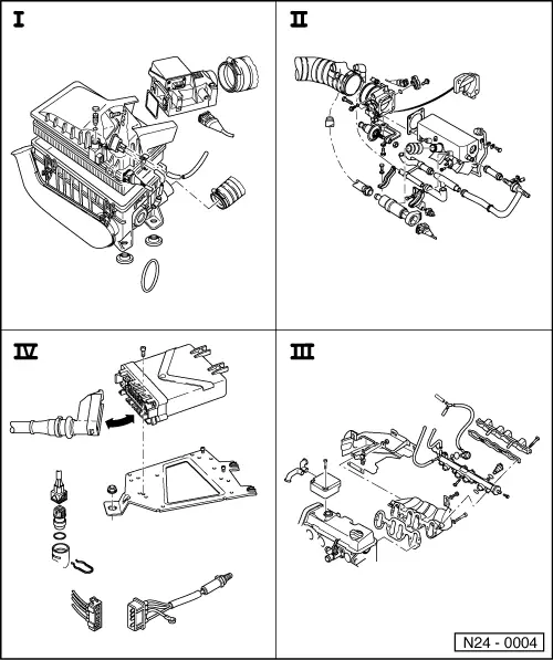
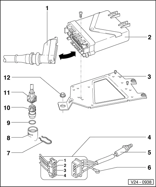
Digifant injection and ignition system
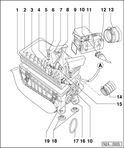
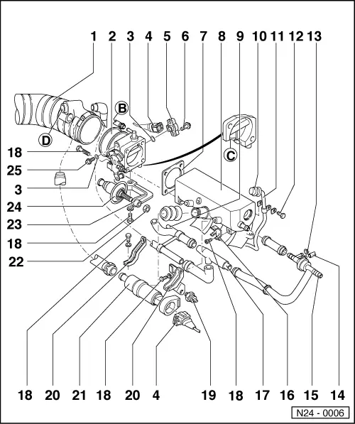
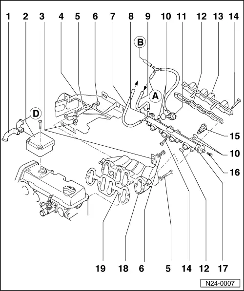
Servicing injection part

Servicing ignition part=>Repair group 28

Notes:

  • ◆ Fuel hoses in engine compartment must only be secured with spring type clips. The use of clamp or screw type clips is not permissible.
  • ◆ The control unit for the fuel injection and ignition system is equipped with a fault memory. Before carrying out repairs, adjustment work and fault finding the fault memory must be interrogated and the vacuum connections checked (outside air).
  • ◆ Components marked with * are checked via the self diagnosis.
    , interrogating and erasing fault memory
  • ◆ Components marked with ** are checked via the final control control diagnosis => Page 01-12 .
  • ◆ For trouble-free operation of the electrical components a voltage of at least 11.5 V is necessary.
  • ◆ Do not use sealants containing silicone. Particles of silicone drawn into the engine, will not be burnt in the engine and damage the Lambda probe.

Safety precautions

Rules for cleanliness => Page 24-24

Technical data => Page 24-25

Self diagnosis and electrical check of the injection and ignition system => Repair group 01

Checking intake system for leaks (unmetered air) => Page 24-54

 
N24-0004
  •      I -     Removing and installing air cleaner and air flow meter
    => Page 24-7
  •      II -     Removing and installing throttle valve housing and idling stabilization valve
    => Page 24-10
  •      III -     Removing and installing fuel manifold and intake manifold => Page 24-16
  •      IV -     Removing and installing control unit, Lambda probe and coolant temperature sender => Page 24-19
 
N24-0005

Removing and installing air cleaner and air flow meter

  •      A -     => Page 24-16
  • Filter element
  • Air cleaner upper part
  • CO Potentiometer (G74)*
    • ◆ Checking resistance
      , Test step 10
    • ◆ The resistance is altered with the CO adjustment screw during idling adjustment
  • O ring
    • ◆ Renew if damaged
  • CO Adjustment screw
    • ◆ Idling speed check
 
N24-0005
  • Plug
  • Air ducting
  • 5 Nm
  • Seal
    • ◆ Renew if damaged
  • Connector
  • Air mass meter*
    • ◆ With sender for intake air temperature (G42) and potentiometer (G19)
    • ◆ After renewing:
      Match Digifant control unit to engine by completing idling check
      => Page 24-26
  • Metal plug
    • ◆ Do not pull out
 
N24-0005
  • Intake hose
  • Hose
    • ◆ To exhaust manifold
  • Temperature regulator
    • ◆ For intake air preheating
    • ◆ Installation position: brass hose connection at bottom
    • ◆ Checking intake air preheating
  • Vacuum unit
    • ◆ Checking intake air preheating
  • Retaining ring
  • Packing
  • Air cleaner lower part
 
N24-0006

Removing and installing throttle valve housing and idling stabilization valve

  •      B -     => Page 24-16
  •      C -     To activated charcoal filter cut-off valve
    • ◆ => Page 24-59 , vacuum hose connection diagram
  •      D -     => Page 24-16
  • Intake hose
 
N24-0006
  • Throttle valve housing
    • ◆ Throttle valve basic setting => Page 24-56
    • ◆ After basic setting:
      Match Digifant control unit to engine by completing idling check
      => Page 24-39
    • ◆ After renewing:
      Match Digifant control unit to engine by completing idling check
      => Page 24-39
 
N24-0006
  • O ring
    • ◆ Renew if damaged
  • Connector
  • Throttle valve potentiometer (G69)*
    • ◆ 3-pin connector for injection and ignition system
    • ◆ 4-pin connector additional on vehicles with automatic gearbox to control unit for automatic gearbox (J217)
    • ◆ Checking => Page 24-38
    • ◆ After renewing:
      Match Digifant control unit to engine by completing idling check
      => Page 24-39
 
N24-0006
  • Bolt
    • ◆ Lock with paint
  • Seal
    • ◆ Renew
  • Intake manifold
  • To activated charcoal filter cut-off valve
    • ◆ => Page 24-59 , vacuum hose connection diagram
  • Plug
  • CO take-off pipe
  • 10 Nm
  • Plug
  • For air conditioner
  • To brake servo
 
N24-0006
  • Bracket
    • ◆ For vacuum booster
  • Vacuum booster
    • ◆ On vehicles with automatic gearbox
  • M6 = 10 Nm
    M8 = 20 Nm
  • Temperature switch
    • ◆ For fan run-on, to cool the injectors
    • ◆ Checking:

=> Repair Group 19; removing and installing parts of cooling system; checking radiator fan run-on

  • Support bracket
  • Idling speed stabilization valve (N71)**
    • ◆ Checking idling stabilization
    • ◆ Resistance: 2...10 ω
 
N24-0006
  • 20 Nm
  • Bracket
    • ◆ For throttle closing damper
  • Throttle closing damper
    • ◆ Only on vehicles with manual gearbox
    • ◆ Checking and adjusting
  • Idling adjustment screw
    • ◆ Idling check
 
N24-0007

Removing and installing fuel manifold and intake manifold

  •      A -     => Page 24-7
  •      B -     => Page 24-10
  •      D -     => Page 24-10
  • Connecting hose
    • ◆ To crankcase breather
  • Crankcase breather pressure regulating valve
  • Bracket
  • Warm air collector plate
  • 25 Nm
  • 20 Nm
 
N24-0007
  • Return hose
    • ◆ Blue or blue markings
    • ◆ Secure with spring-type clips
  • Retaining clip
  • Supply hose
    • ◆ Black or white markings
    • ◆ Secure with spring-type clips
  • O ring
    • ◆ Renew if damaged
  • Fuel pressure regulator
    • ◆ Checking fuel pressure regulator and holding pressure => Page 24-45
  • Seal
    • ◆ Renew if damaged
 
N24-0007
  • Fuel manifold upper part
    • ◆ Removing and installing:
      => Page 24-48 , removing and installing injectors
  • 10 Nm
  • Injectors (N30...N33)
    • ◆ Removing and installing
      => Page 24-48
    • ◆ Checking => Page 24-51
  • Sealing plug
    • ◆ For test connection
  • Fuel rail
    • ◆ Removing and installing:
      => Page 24-48 , removing and installing injectors
  • Intake manifold
  • Seal
    • ◆ Renew
 
V24-0938

Removing and installing control unit, Lambda probe and coolant temperature sender

  • Connector
    • ◆ Only disconnect or connect with ignition switched off
  • Digifant control unit (J169)*
    • ◆ For injection system, Lambda regulation, engine speed governor via fuel pump relay, ignition and self diagnosis
    • ◆ After renewal:
      Match Digifant control unit to engine by completing idling check => Page 24-26
  • Bracket
 
V24-0938
  • Connector
    • ◆ For Lambda probe and Lambda probe heating
    • ◆ Check Lambda probe heating voltage supply between contacts -1- (red/white) and -2- (brown/black) with engine running:
           Specification:
           approx. battery voltage
    • ◆ Check Lambda probe heating at Lambda probe connector (white wiring) for continuity
    • ◆ Contact 3 - Lambda probe screening
    • ◆ Contact 4 - Lambda control
 
V24-0938
  • Lambda probe (G39)*, 50 Nm
    • ◆ Fitting location: catalyst
    • ◆ Grease only the threads with "G5"; "G5" must not get into the slots on the probe body
    • ◆ Checking Lambda probe and Lambda control
      => Page 24-32
    • ◆ Note various versions
      => Page 24-23 , Fig. 1
  • Earth wire
  • Retaining clip
  • Connection
  • O ring
    • ◆ Renew if damaged
 
V24-0938
  • Coolant temperature sender (G62)*
    • ◆ With coolant temperature indicator sender (G2)
    • ◆ If necessary before removing, release pressure from cooling system
    • ◆ Resistance values
      => Page 01-28 , Fig. 1
  • Connector
  • 10 Nm
 
N24-0061

→ Fig. 1     Types of Lambda probe

  •      1 -     Heated Lambda probe
    • (A - drilling) for vehicles without catalyst
  •      2 -     Heated Lambda probe
    • (B - slot) for vehicles with catalyst

Safety precautions > < Fitting locations overview