-
‒ →
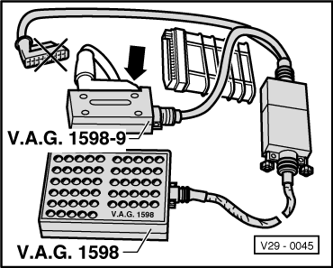
With ignition switched off, pull connector off Digifant control unit (J169). (The control unit is located right in plenum chamber).
-
‒ Connect test box V.A.G 1598 with adapter cable V.A.G 1598-9 to wiring loom connector only (control unit remains disconnected).
-
‒ Carry out checks as per table
.
Attention!
To prevent damage to the electronic components, switch to the respective measuring range before connecting the measuring cable, observe the test conditions and carry out the additional work listed in the table.
Note:
After completing the electrical check, on vehicles with automatic gearbox, the fault "Engine/gearbox electrical connection: open circuit"caused by the check and stored in the automatic gearbox control unit must be erased.
=> Automatic gearbox 096; Repair Group 01; Self diagnosis; Erasing fault memory
Test table
|
- Measuring range: Switch to voltage measurement -V-.
|
|
Test step
|
Item checked
|
▪ Test conditions
- additional work
|
Test box sockets
|
Specifications1)
|
|
1
|
Voltage supply for Digifant control unit (J169)
|
- Switch on ignition
|
20 + 36
29 + 38
|
app. battery voltage
|
|
2
|
Wire to ignition trans. (N152)
|
▪ Ignition switched on
|
20 + 27
|
app. battery voltage
|
|
3
|
Idling stabilization valve
(N71)
|
▪ Ignition switched on
|
25 + 29
|
app. battery voltage
|
|
4
|
Wire to fuel pump relay (J17) with relay
|
▪ Ignition switched on
|
bridge
7 + 29
|
Fuel pump must run audibly
|
|
5
|
Wire to the injectors (N30...N33)2)
|
▪ Ignition switched on
Remove fuse 18
Bridge sockets 7 + 29
|
2 + 20
|
app. battery voltage
|
1)
Observe notes => Page 01-16
2)
Checking injector resistance => Page 24-52
|
▪ Measuring range: Voltage measurement range -V- selected.
|
|
Test step
|
Item checked
|
▪ Test conditions
- additional work
|
Test box sockets
|
Specifications1)
|
|
62)
|
Wire to air conditioner
|
▪ Ignition switched on
Switch on heater blower
Switch air conditioner to maximum
|
20 + 37
|
app. battery voltage
|
|
7
|
Wire from starter terminal 50
|
▪ Selector lever in P or N
Pull connector off Hall sender (distributor)
Operate starter and then switch off ignition
|
26 + 29
|
at least 8 V
|
1)
Observe notes => Page 01-16
2)
Only vehicles with air conditioner; vehicles with Climatronic =>Test step 20
|
▪ Ignition switched off
▪ Measuring range: Resistance measurement -ω- selected
|
|
Test step
|
Item checked
|
▪ Test conditions
- additional work
|
Test box sockets
|
Specifications1)
|
|
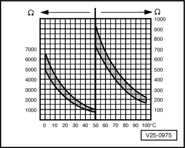
82)
|
Coolant temperature sender (G62)
|
---
|
13 + 14
|
=> Page 01-28
,
=> Fig. 1
|
|
9
|
Intake air temperature sender (G42)
|
---
|
13 + 15
|
=> Page 01-28
,
=> Fig. 1
|
|
10
|
CO Potentiometer (G74)
|
---
|
13 + 35
|
0...2 kω
|
|
11
|
Air flow meter potentiometer (G19)
|
---
|
13 + 28
|
0.5...1.0 kω
|
|
|
|
- Move air flow meter plate or operate starter
|
19 + 28
|
Change in resistance
|
1)
Observe notes => Page 01-16
2)
If the self diagnosis indicates a sender fault which is not established by this test, it could be caused by a temporary break in the temperature signal. In this case, additionally check the coolant temperature sender => Page 24-39
.
|
▪ Ignition switched off
▪ Measuring range: Resistance measurement -ω- selected
|
|
Test step
|
Item checked
|
▪ Test conditions
- additional work
|
Test box sockets
|
Specifications1)
|
|
12
|
Wiring to throttle valve potentiometer (G69)
|
- Pull 3-pin connector off throttle valve potentiometer
|
1 +
Contact 12)
12 +
Contact 22)
13 +
Contact 32)
|
max. 1.5 ω
|
|
13
|
Wiring to Hall sender
(G40)
|
- Pull connector off G40 (distributor)
|
13 +
Contact 13)
11 +
Contact 23)
30 +
Contact 33)
|
max. 1.5 ω
|
1)
Observe notes => Page 01-16
2)
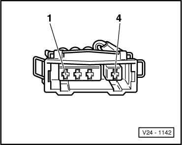
On separated connector for G69 => Page 01-30
, Fig. 3
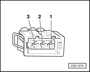
3)
On separated connector for G40 => Page 01-29
, Fig. 2
|
▪ Ignition switched off
▪ Measuring range: Resistance measurement -ω- selected
|
|
Test step
|
Item checked
|
▪ Test conditions
- additional work
|
Test box sockets
|
Specifications1)
|
|
14
|
Wiring to knock sensor 1 (G61)
|
- Separate connector to G61
|
16 +
Contact 12)
|
max. 1.5 ω
|
|
|
|
|
17 +
Contact 22)
|
|
|
|
|
|
34 +
Contact 32)
|
|
|
15
|
Wiring to Lambda probe
(G39)
|
- Separate connector to G39
|
20 +
Contact 13)
|
max. 1.5 ω
|
|
|
|
|
8 +
Contact 43)
|
|
|
|
|
- Reconnect connector to G39
|
8 + 20
|
∞ω
|
1)
Observe notes => Page 01-16
2)
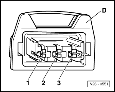
On separated connector for G61 => Page 01-30
, Fig.6
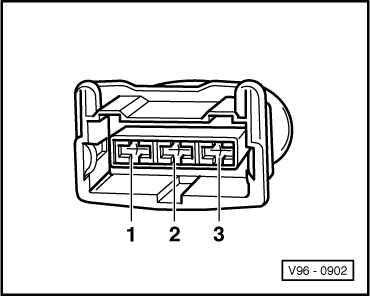
3)
On separated connector for G39 => Page 01-29
, Fig.3
|
▪ Ignition switched off
▪ Measuring range: Resistance measurement -ω- selected
|
|
Test step
|
Item checked
|
▪ Test conditions
- additional work
|
Test box sockets
|
Specifications1)
|
|
16
|
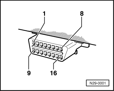
Wire to diagnostic socket
|
---
|
32 +
Contact 72) on diagnostic socket
|
Max. 1.5 ω
|
1)
Observe notes => Page 01-16
2)
Pin assignment => Page 01-28
, Fig. 2
Checks with Digifant control unit connected
|