volkswagen Workshop Repair Guides

Volkswagen Workshop Service and Repair Manuals

Electrical check > < Fault table
Digifant Injection and Ignition System
Self diagnosis
Final control diagnosis

The final control diagnosis activates the following components in the stated sequence:

1. Fuel pump relay (J17)

2. Idling speed stabilisation valve (N71)

  • ‒ Connect fault reader V.A.G 1551 and select engine electronics control unit (address word 01); carry out selection with ignition switched on.
 
→ Indicated on display:
Rapid data transfer     HELP
Select function XX
  • ‒ Operate fault reader taking into account the information on the display:
  • ‒ Input 03 for "Final control diagnosis" function.
 
→ Indicated on display:
Rapid data transfer     Q
03 Final control diagnosis

Note:

If something different is indicated on the display:

=> Fault reader operating instructions

Actuate fuel pump relay (J17):

  • ‒ Confirm input with Q button.
 
→ Indicated on display:
Final control diagnosis     ⇒
Fuel pump relay J17
  • The fuel pump relay (on the relay plate with fuse box, relay position 12) must click until switching to the next final control by pressing the ⇒button.

Note:

During the activation of the fuel pump relay the fuel pump must be heard to run at intervals.

If the relay does not click:

  • ‒ Check fuel pump relay:

=> Current flow diagrams, Electrical fault finding and Fitting locations; Fuel supply.

Activate idling stabilization valve (N71):

  • ‒ Press ⇒key.
 
→ Indicated on display:
Final control diagnosis     ⇒
Idling stabilization valve N71
  • The idling stabilization valve must click.

If idling speed stabilization valve clicks:

  • ‒ Press ⇒ button.
 
→ Indicated on display:
Rapid data transfer     HELP
Select function XX
  • ‒ Input 06 for "End output" function and confirm with Q.
  • ‒ Switch off ignition

Notes:

  • ◆ If ignition is not switched off before trying to start engine, engine will not start as the injectors and ignition transformer will not have been activated.
  • ◆ If final control diagnosis has to be repeated, switch off ignition, disconnect lead from fault reader for at least 3 minutes, re-connect and carry out final control diagnosis.

If the idling stabilization valve does not click:

 
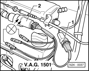
N24-0037
  • ‒ → Pull plug -1- off valve -2- and connect measuring cable V.A.G 1501 to valve and wiring loom.
  • ‒ Connect diode test lamp V.A.G 1527 with adapters from V.A.G 1594 to connectors 1 and 3 of the measuring cable.
         LED must flash

LED flashes or lights up:

  • ‒ Renew idling stabilization valve.

LED does not flash or light up:

  • ‒ Press ⇒ button.
 
→ Indicated on display:
Rapid data transfer     HELP
Select function XX
  • ‒ Input 06 for "End output" function and confirm with Q.
  • ‒ Switch off ignition
  • ‒ Carry out electrical check, Test step 3
    => Page 01-16 , renew control unit if necessary.

Electrical check > < Fault table