volkswagen Workshop Repair Guides

Volkswagen Workshop Service and Repair Manuals

Checking Lambda probe ageing Lambda probe before catalyst > < Check Lambda probe and Lambda control after catalyst
Motronic fuel injection and ignition system 08.95 ä
Motronic injection and ignition system
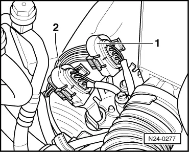
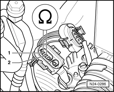
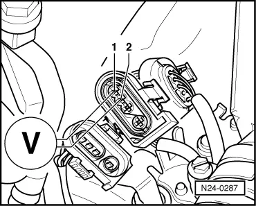
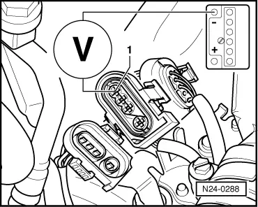
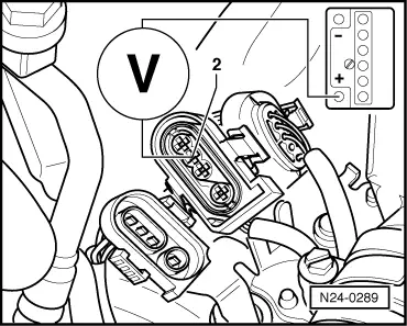
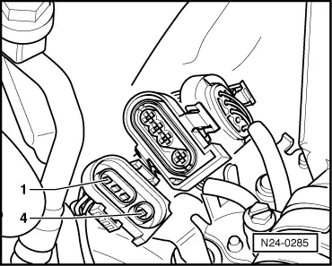
Check Lambda probe heating after catalyst

Special tools, testers and auxiliary items

  • ◆ Fault reader V.A.G 1551 or vehicle system tester V.A.G 1552 with cable V.A.G 1551/3
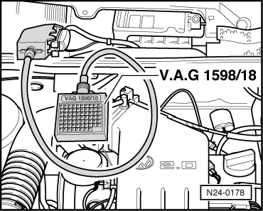
  • ◆ Test box V.A.G 1598/18
  • ◆ Hand multimeter V.A.G 1526 or multimeter V.A.G 1715
  • ◆ Adapter set V.A.G 1594
  • ◆ Current flow diagram

Test conditions

  • ● Fuse 18 OK.

Test sequence

  • ‒ Connect fault reader V.A.G 1551 (V.A.G 1552) and select engine electronics control unit with the "Address word" 01. When doing this the engine must be running at idling speed.
    (Connecting fault reader and selecting engine electronics control unit .)
 
→ Indicated on display:
Rapid data transfer     HELP
Select function XX
  • ‒ Press keys 0 and 8 for the function "Read measured value block" and confirm entry with Q key.
 
→ Indicated on display:
Read measured value block     HELP
Input display group number XXX
  • ‒ Press keys 1, 2 and 1 for "Display group number 121" and confirm entry with Q key.
 
→ Indicated on display:
(1...4 = Display zones)
Read measured value block 121     ⇒
     1     2     3     4
  • ‒ Check resistance value for Lambda probe heating after catalyst (display zone 3):

Display zones

1

2

3

4

Display group 121: Lambda probe heating after catalyst

Display

xxx.x °C

xxx.xx s

x.x ω

xxxxxxxx

Indicated

Catalyst temperature

Time from heating on to diagnosis start

Lambda probe heating resistance (after catalyst)

Lambda control status after catalyst

Working range

0.0...999.9 °C

Approx.150.00 s

0.0...65.0 ω

Relevance

Specification

---

---

5.9...24.2 ω

---

---

If specification is not attained , continuation

---

  • ‒ Press ⇒key.
  • ‒ Press keys 0 and 6 for the "End data transfer" function and confirm input with the Q key.
  • ‒ Switch off ignition.

Relevance of figures in 8 digit number block

Relevance when display = 1

x

x

x

x

x

x

x

x

Lambda control status (display group 121)

1

Fault in fault memory

1

Fault detected during this diagnosis

1

Diagnosis complete during this drive

1

Diagnosis currently active

1

Probe heating after catalyst ready

1

Lambda probe after catalyst ready

1

Vapour point after catalyst exceeded

1

1 = Probe heating after catalyst on
alternately 0 and 1 = Probe heating is phased

Continuation

 
N24-0277
  • ‒ → Separate 4 pin connector (brown) to Lambda probe after catalyst (G108) -2-.
 
N24-0286
  • ‒ → Connect multimeter with aux. cables from V.A.G 1594 to measure resistance at contacts 1+2 on connector to Lambda probe.
  • ‒ Measure the resistance value.
         Specification: 0.00...24.2 ω

If the specification is not attained:

  • ‒ Renew the Lambda probe after catalyst (G108).

If the specification is attained:

  • ‒ Set multimeter to "Voltage measurement" range.
 
N24-0287
  • ‒ → Connect multimeter with aux. cables from V.A.G 1594 to measure voltage at contacts 1+2 of connector to engine control unit.
  • ‒ Measure the voltage supply:
    When display group 121, display zone 4, 1st position from left = 1
         Specification: 11.0...14.5 V
    When display group 121, display zone 4, 1st position from left = alternating 0 and 1
         Specification: Between 0.0...12.0 V fluctuating

If no voltage is present:

 
N24-0288
  • ‒ → Connect multimeter using aux. cables from V.A.G 1594 to measure voltage at contact 1 (connector to Motronic control unit) and vehicle earth.
         Specification: 11.0...14.5 V

If again no voltage is present:

  • ‒ Check the wiring from contact 1 to relay plate according to current flow diagram.

If voltage was present:

 
N24-0289
  • ‒ → Connect multimeter with aux. cables from V.A.G 1594 to contact 2 (connector to Motronic control unit) and battery +.
    When display group 121, display zone 4, 1st position from left = 1
         Specification: 11.0...14.5 V
    When display group 121, display zone 4, 1st position from left = alternating 0 or 1
         Specification: Between 0.0...12.0 V fluctuating
  • ‒ Switch off ignition.

If the specification is not attained:

 
N24-0178
  • ‒ → Connect test box V.A.G 1598/18 to control unit wiring loom -arrow-.
 
N24-0285
  • ‒ → Check wiring between test box and 4 pin connector for open circuit according to current flow diagram.
         Contact 2+socket 66
         Wire resistance: Max. 1.5 ω

If no wiring fault is detected:

  • ‒ Replace Motronic control unit (J220).
  • ‒ Read-out the readiness code=> Page 01-34 .

Checking Lambda probe ageing Lambda probe before catalyst > < Check Lambda probe and Lambda control after catalyst