
Passat (B3)
| → Indicated on display: |
|
||
|
| → Indicated on display: |
|
||
|
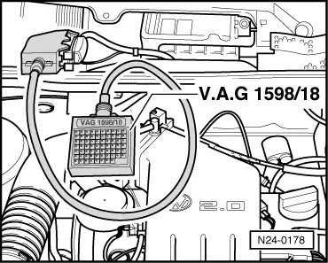
| →
Indicated on display: (1...4 = Display zones) |
|
||
|
Note: If something different is indicated on the display: => Fault reader operating instructions
If the displayed figure fluctuates or the battery voltage is not attained:
|
 |
|
If the specifications are not attained:
Checking voltage supply terminal 30
If the specification is not obtained:
Checking voltage supply terminal 15
If the specification is not obtained:
|