volkswagen Workshop Repair Guides

Volkswagen Workshop Service and Repair Manuals

Checking driving range signal > < Checking speed signal
Motronic injection and ignition system (6-Cyl. engine)
Checking additional signals
Checking air conditioner compressor signal

Air conditioner compressor signal:
Voltage is supplied to the engine control unit shortly before switching on the air conditioner compressor. The signal ensures that the control unit keeps the idling speed constant for the differing power requirements of the air conditioning system.

Air conditioner cut-off:
The air conditioner compressor is switched off for approx. 12 seconds by the engine control unit when accelerating from standstill and from low speeds to ensure that the full engine power is available when accelerating. If the accelerator is released earlier the time is shortened to a minimum of 3 seconds. At full throttle the air conditioner is switched off by the gearbox control unit (Kick-down switch).

Special tools, testers, measuring instruments and auxiliary items required

  • ◆ Fault reader V.A.G 1551 or vehicle system tester V.A.G 1552 with cable V.A.G 1551/3
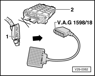
  • ◆ Test box V.A.G 1598/18
  • ◆ Hand multimeter V.A.G 1526 or multimeter V.A.G 1715
  • ◆ Adapter set V.A.G 1594
  • ◆ Current flow diagram

Test conditions

  • ● Air conditioner functioning OK.
  • ● Air conditioner must be switched off
  • ● No faults must be stored in fault memory
    , interrogating fault memory
  • ● Vehicle at room temperature (warmer than + 15 °C).

Test sequence

  • ‒ Connect fault reader V.A.G 1551 (V.A.G 1552). Start engine and select "Address word" 01 of engine control unit. When doing this the engine must be running at idling speed.
    (Connecting fault reader and selecting engine control unit => Page 01-5 .)
 
→ Indicated on display:
Rapid data transfer     HELP
Select function XX
  • ‒ Press keys 0 and 8 for the function "Read measured value block" and confirm entry with Q key.
 
→ Indicated on display:
Read measured value block     HELP
Input display group number XXX
  • ‒ Press keys 0, 1 and 3 for "Display group number 13" and confirm entry with Q key.
 
→ Indicated on display:
(1...4 = Display zones)
Read measured value block 13     ⇒
     1     2     3     4
  • ‒ Observe display in display zone 4. It must show
         Compr. OFF.
  • ‒ Switch on air conditioning system.
  • ‒ Select lowest temperature and highest blower speed.
  • The display in display zone 4 must change to
         Compr. ON.
  • ‒ Floor accelerator pedal quickly and release again (short throttle burst).
  • When quickly pressing the accelerator pedal down the display in display zone 4 must change from "ON" to "OFF" for a few seconds (compressor cut-off for vehicle acceleration).
  • ‒ Press the ⇒key.
 
V29-0062
  • ‒ Press keys 0 and 6 for the "End output" function and confirm input with the Q key.
  • ‒ Switch off ignition.

If the display does not change:

  • ‒ → Connect test box V.A.G 1598/18 to control unit wiring loom.
  • ‒ Check wiring between test box sockets 37 and 38 to air conditioner for open circuit using current flow diagram.
         Wire resistance: Max. 1.5 ω

If no fault can be found in the wiring:

  • ‒ Check function of air conditioner control unit.

=> Air conditioner; Repair group 01; Air conditioning system self-diagnosis

Checking driving range signal > < Checking speed signal