-
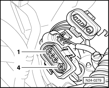
‒ Pull relay for Lambda probe heating (J278) out from relay chamber.
=> Current flow diagrams, Electrical fault finding and Fitting locations binder
-
‒ →
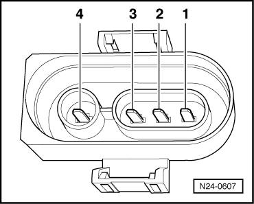
Check wiring between 4 pin connector contact 1 + chamber 8 on relay connector for open circuit according to current flow diagram:
Specification: max.1.5 ω
-
‒ Additional check wiring between connector contact 2 + engine earth for open circuit:
Specification: max.1.5ω
-
‒ Check wiring for short circuit to one another
Contact 1 + 2
Specification: ∞ω
-
‒ Switch on ignition.
-
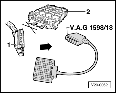
‒ Bridge test box sockets 1+9.
-
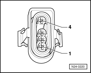
‒ Measure activation voltage at relay chamber pin 6:
-
Specification: At least 11.5 V
No voltage is displayed:
-
‒ Check wiring to current supply relay (J271) according to current flow diagram.
If no wiring fault is detected:
-
‒ Renew current supply relay (J271).
-
‒ Then bridge test box sockets 1+6.
-
‒ Measure activation voltage of relay connector 2:
-
Specification: At least 11.5 V
If no voltage was present:
-
‒ Check wire from fuse 18 to relay chamber pin 2 for open circuit.
If not open circuit can be found:
-
‒ Check wire between test box socket 28 and relay chamber pin 4 for open circuit using current flow diagram.
Specification: Max. 1.5 ω
If the specifications are attained:
-
‒ Renew Lambda probe heating relay (J278).
|