-
‒ →
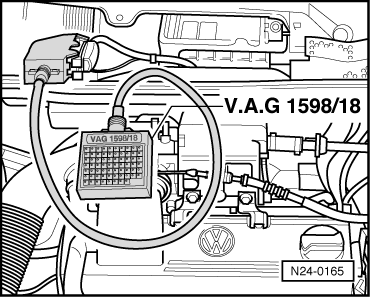
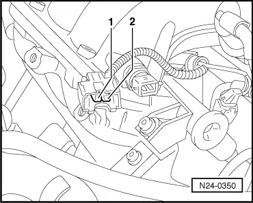
Check wiring between test box and 2 pin connector for open circuit according to current flow diagram.
Contact 1+socket 37
Contact 2+socket 35
Wire resistance: Max. 1.5 ω
Continued for all engine codes
-
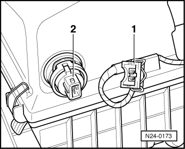
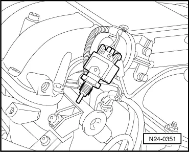
‒ Check wire between control unit connector and 2 pin connector contact 2 for short to wire contact 1 and to vehicle earth, according to current flow diagram.
Contact 2+socket 37
Specification: ∞ω
-
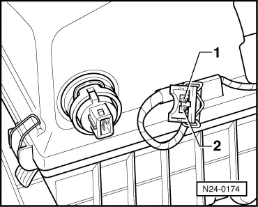
‒ Check wire between control unit connector and 2 pin connector contact 2 for short to wire contact 1 and to vehicle earth, according to current flow diagram.
Contact 2+socket 37
Specification: ∞ω
-
‒ Additionally check wiring for short to battery positive.
Specification: ∞ω
If no fault in wire is detected:
-
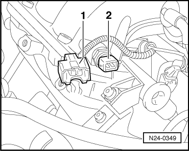
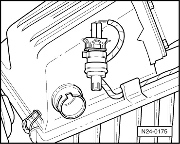
‒ Perform resistance measurement on intake air temperature sender (G42) contacts 1+2, resistance figures => Page 24-30
, Fig. 1
If the specification is not obtained:
-
‒ Renew intake air temperature sender (G42)
, item 18
.
|