
Passat (B3)
| Removing and installing subframe, anti-roll bar and suspension link (Plus running gear) |

| 1 - | Hexagon bolt, 35 Nm |
| 2 - | Swivel joint |
| q | Checking → Chapter. |
| q | Check rubber boot for damage, renew swivel joint if necessary. |
| q | Removing and installing → Chapter. |
| q | Mark installation position; if suspension link is renewed, set to centre of elongated hole and check toe setting. |
| 3 - | Self-locking hexagon nut, 45 Nm |
| 4 - | Plate with nuts |
| 5 - | Rear suspension link bush |
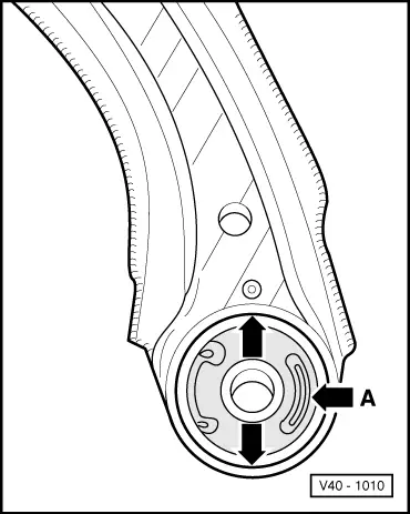
| q | Installation position → Fig.. |
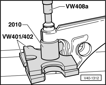
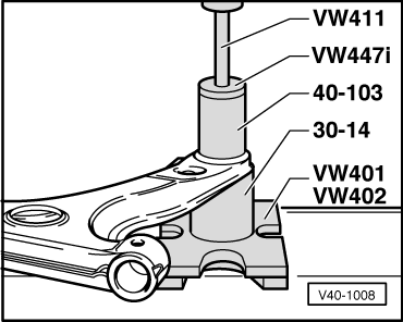
| q | Pressing out and in → Fig.. |
| 6 - | Suspension link |
| q | Elongated holes are not used to set camber! |
| 7 - | Air guide |
| q | Secured to suspension link with a clip. |
| 8 - | Front suspension link bush |
| q | Pressing out and in → Fig.. |
| 9 - | Hexagon bolt M12 x 1.5 x 78 |
| q | 70 Nm and turn 90° further. |
| 10 - | Hexagon bolt M12 x 1.5 x 65 |
| q | 70 Nm and turn 90° further. |
| 11 - | Coupling rod |
| q | With rubber bush. |
| 12 - | Mounting for coupling rod |
| q | Conical side to suspension link. |
| 13 - | Washer |
| q | Collar faces away from mounting. |
| 14 - | Self-locking hexagon nut, 20 Nm |
| 15 - | Hexagon bolt M12 x 1.5 x 82 |
| q | 50 Nm and turn 90° further. |
| 16 - | Hexagon nut, 25 Nm |
| 17 - | Hexagon bolt, 25 Nm |
| q | To secure anti-roll bar. |
| 18 - | Hexagon bolt, 65 Nm |
| 19 - | Anti-roll bar clamp |
| 20 - | Vibration damper |
| q | Not fitted in vehicles with VR6 engine. |
| 21 - | Subframe |
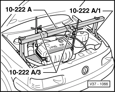
| q | Removing and installing when assemblies are installed: support assemblies → Fig.. |
| q | Take subframe with suspension links (but without steering box) out downwards using engine and gearbox jack -V.A.G 1383 A-. After installing, check front wheel alignment and position of steering wheel. |
| q | Aligning engine/gearbox assembly → Engine; Rep. Gr.10. |
| 22 - | Anti-roll bar bush |
| 23 - | Anti-roll bar |
| q | 24 mm Ø. |
| 24 - | Cap nut |
| q | Reworking in longitudinal member → Chapter. |
 Note
Note
|
|
|
|
|
|