volkswagen Workshop Repair Guides

Volkswagen Workshop Service and Repair Manuals

Vehicle electrics > < Checking exhaust gas recirculation valve (mechanical)
3-cyl. diesel engine, Mechanics
Exhaust gas recirculation system
Checking exhaust gas recirculation
 
W26-0008

Special tools, workshop equipment, test and measuring appliances and auxiliary items required

  • ◆ V.A.G 1526 Hand multimeter
  • ◆ V.A.G 1594 A Adapter set
  • ◆ V.A.G 1598/31 Test box
  • ◆ Fault reader V.A.G 1551 or vehicle system tester V.A.G 1552 with cable V.A.G 1551/3
  • ◆ Current flow diagram

Test sequence

The exhaust gas recirculation function is checked in function 04 (basic setting). With this method, the EGR valve (electric) is pulsed every 10 seconds so that the extreme values for exhaust gas recirculation (air mass meter) measured value block 003 can be read in display zone 3.

  • ‒ With engine running at idle speed, connect fault reader V.A.G 1551 (V.A.G 1552) and select engine electronics control unit with the "Address word" 01:

=> Repair group 01; Self-diagnosis; Connecting fault reader V.A.G 1551 and selecting engine electronics control unit

 
→ Indicated on display:
Rapid data transfer    HELP
Select function XX
  • ‒ Press keys 0 and 4 for the function "Introduction of basic setting" and confirm entry with Q key.
 
→ Indicated on display:
Basic setting    HELP
Input display group number XXX
  • ‒ Press keys 0, 0 and 3 for "Display group number 3" and confirm entry with Q key.

Note:

After you have selected display group 3 and confirmed with the Q key, the engine idling speed in display zone 1 will be raised by the engine control unit to 1350...1450 rpm.

 
→ Indicated on display:
(1...4 = Display zones)
System in basic setting    3    ⇒
    1400 rpm    EGRn.active     500 mg/H    20%
  • The display in display zone 2 must fluctuate every 10 secs. between EGR active and EGRn.active.
  • The displays in display zones 3 and 4 must fluctuate within following control range:

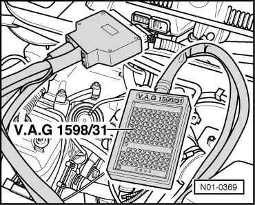
Note:

If a constant value of 539 mg/H is indicated in display zone 3, check air mass meter

=> Repair group 23; Servicing Diesel direct injection system; Checking air mass meter

EGRn.active

  • ‒ Specification display zone 3
        450...600 mg/H (mg per capacity of one cylinder)
  • ‒ Specification display zone 4
        20%

EGR.active

  • ‒ Specification display zone 3
        160...310 mg/H (mg per capacity of one cylinder)
  • ‒ Specification display zone 4
        65 %

If the specifications are not attained:

  • ‒ Check mechanical exhaust gas recirculation valve
  • ‒ Check vacuum hoses => Page 26-10
  • ‒ Check EGR valve (N18) as follows:
  • ‒ Press the ⇒key.
 
N23-0016
  • ‒ Press keys 0 and 6 for the "End data transfer" function and confirm input with the Q key.
  • ‒ Switch off ignition.
  • ‒ → Pull connector off EGR valve -2-.
  • ‒ Measure resistance at valve.
        Specification: 14 ... 20 ω

If the specification is not obtained:

  • ‒ Replace EGR valve (N18).
 
N24-0231

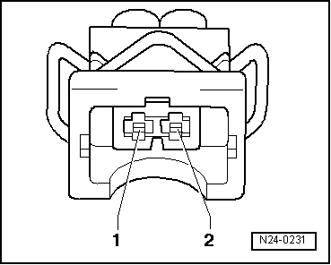
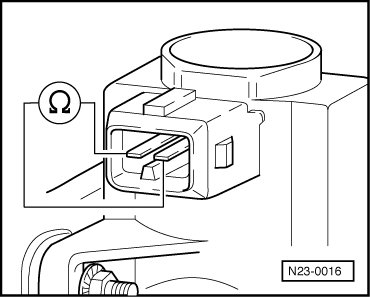
Note:

At room temperature the resistance lies in the the lower tolerance region and at operating temperature in upper tolerance region.

If the specification is obtained:

  • ‒ Switch on ignition.
  • ‒ → Measure supply voltage at valve connector contact 1 and at engine earth.
        Specification: approx. battery voltage

If the specification is not obtained:

 
N01-0369
  • ‒ Switch off ignition.
  • ‒ → Connect test box V.A.G 1598/31 to control unit wiring harness.
  • ‒ Check wiring between test box and connector for open circuit using current flow diagram.
        Contact 1+ socket 1 + 2
        Contact 2+ socket 61
        Wire resistance: max. 1.5 ω
  • ‒ Additionally check wires for short to one another, to vehicle earth and to battery positive.
        Specification: ∞ω

If no fault is detected in the wiring:

  • ‒ Renew Diesel direct injection system control unit (J248)

=> Repair group 23; Renewing engine control unit, coding and matching; Renewing engine control unit

Vehicle electrics > < Checking exhaust gas recirculation valve (mechanical)