volkswagen Workshop Repair Guides

Volkswagen Workshop Service and Repair Manuals

Dismantling and assembling selector mechanism on vehicles from 07.99 > < Dismantling and assembling selector mechanism on vehicles with ignition key removal lock from 06.99
Automatic gearbox 001
Servicing gear change mechanism
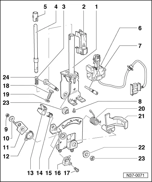
Dismantling and assembling selector lever on vehicles with ignition key removal lock up to 06.99
 
N37-0071

Selector lever must be removed to renew individual parts

.

Lubricate all mountings and sliding surfaces with Polyurea grease Part No. G 052 142 A2.

  • Selector lever
    • ◆ Assembling => Fig. 1
  • Indicator lighting
    • ◆ Securing indicator lighting connector => Fig. 4
    • ◆ On right-hand drive vehicles there is an additional contact which prevents starting the engine when the "selector lever handle" locking button has been pressed
  • Spring
 
N37-0071
  • Push rod
    • ◆ Grease in area of sliding surfaces
  • Guide sleeve
    • ◆ Fit after installing pressure rod
  • Set screw
    • ◆ Screwed into the push rod
    • ◆ Locates in the detent plate -item15 -
    • ◆ Always renew
    • ◆ To remove set screw, remove solenoid for selector lever lock and scale lighting. Clamp set screw in vice and loosen by turning selector lever.
    • ◆ Install with locking fluid AMV 185 101 A1
 
N37-0071
  • Selector lever lock solenoid -N110-
    • ◆ Adjusting =>Fig. 2
    • ◆ Functional check => Fig. 3
    • ◆ Can be checked electrically and by measured value block

=> Self-diagnosis for automatic gearbox 001; Repair group 01; Performing self-diagnosis; Reading measured value block

  • Screw, 3 Nm
    • ◆ Qty. 2
    • ◆ Install with locking fluid AMV 185 101 A1
  • Nut, 5 Nm
    • ◆ Always renew
  • Washer
  • Locking lever
    • ◆ For ignition key removal lock
    • ◆ Adjust together with locking cable
 
N37-0071
  • Spring
    • ◆ Hook into hole of detent plate
  • Retainer
    • ◆ For locking cable
    • ◆ Removing and installing locking cable
    • ◆ Adjusting locking cable => Page 37-27
  • Spring
    • ◆ For locking pin
  • Detent plate
    • ◆ Assemble selector lever before fitting in selector lever housing => Fig.1
  • Locking pin
    • ◆ With bracket
  • Hexagon socket headed screw,
    6 Nm
 
N37-0071
  • Screw, 6 Nm
  • Washer
  • Spring
    • ◆ Insert in selector lever together with lever -Item 21 -
  • Lever
    • ◆ For locking in selector lever position "N" or "P"
    • ◆ Adjusting =>Fig. 2
  • Bush
  • Nut, 10 Nm
    • ◆ Always renew
  • Combi-bolt
    • ◆ Grease shank
 
N37-0074

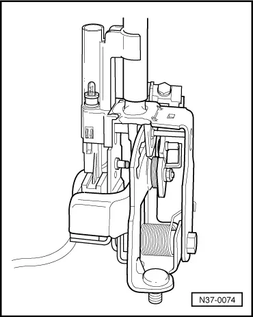
→ Fig.1     Assembling selector lever before installing

Adjust solenoid for selector lever lock -N110- and carry out functional check => Fig. 3 before installing selector lever in selector lever housing.

  • ‒ Install set screw and selector lever lock solenoid -N110- screws with locking fluid AMV 185 101 A1.
 
N37-0075

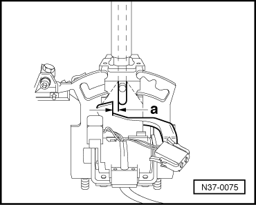
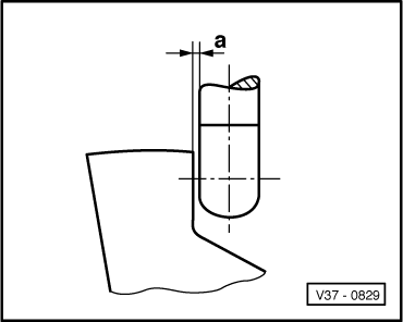
→ Fig.2     Adjusting selector lever lock solenoid -N110-

  • ‒ Adjust solenoid by sliding in elongated holes so that a clearance -a- of 0,3 mm exists between pressure rod and lever => Fig. 3 .
 
V37-0829

→ Fig.3     Adjusting clearance between pressure rod and lever

Dimension a = 0.3 mm

Functional check

  • ‒ Shift selector lever into "P" and supply solenoid with 12 V. It must not be possible to shift selector lever into a driving gear
    • ‒ Interrupt solenoid operation; it must be possible to shift into driving gears.
  • Pressure rod must not catch on lever.
  • ‒ Shift selector lever into "N" and check as in "P".
  • ‒ After adjusting clearance, install assembled selector lever.
 
N37-0072

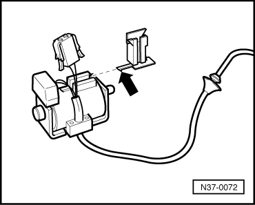
→ Fig.4     Securing indicator lighting connector

  • ‒ Push bracket with lug (arrow) on until lug engages.
  • ‒ Seat connector cable into bracket and slide connector onto bracket.

Dismantling and assembling selector mechanism on vehicles from 07.99 > < Dismantling and assembling selector mechanism on vehicles with ignition key removal lock from 06.99