volkswagen Workshop Repair Guides

Volkswagen Workshop Service and Repair Manuals

Checking speed signal > < Checking speed signal
Checking signal from/to air conditioning system
Special tools and workshop equipment required
t  Fault reader -V.A.G 1551-
t  Diagnosis lead -V.A.G 1551/3C-
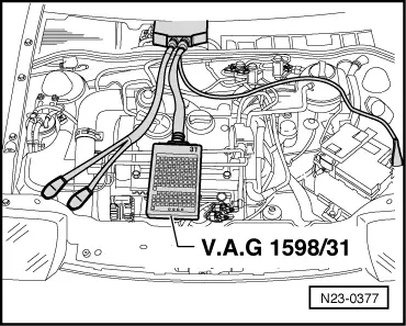
t  Adapter cable, 121-pin -V.A.G 1598/31-
t  Hand multimeter -V.A.G 1526C- or multimeter -V.A.G 1715-
t  Auxiliary measuring set -V.A.G 1594C-
t  Current flow diagram
Test prerequisites
l  The function of the air conditioning system must be OK.
l  No faults must be stored in fault memory → Chapter.
l  Vehicle at room temperature (warmer than + 15 °C).
l  Air conditioning system switched on
Checking compressor shut-off
The engine control unit receives the information that the air conditioner will be switched on shortly via the air conditioner ready signal.
Through another wiring connection, the engine control has the possibility of switching off the air conditioner compressor for various operating conditions:
t  Hard acceleration from low speed
t  Emergency programme (emergency running operation)
t  Coolant temperatures above + 120 °C
t  Each start sequence for approx. 6 seconds.
Test procedure
–  Connect fault reader -V.A.G 1551- and select engine electronics control unit with “address word 01”. Engine must be idling. (Connecting fault reader and selecting engine electronics control unit → Chapter.)
   
Indicated on display:
–  Press buttons 0 and 3 for function “final control diagnosis”.
 
Rapid data transfer                 HELP
Select function XX                      
Indicated on display:
–  Confirm entry with Q button.
 
Rapid data transfer                    Q
03-Final control diagnosis              
Indicated on display:
–  Press the button.
 
Final control diagnosis               ->
Exhaust gas recirculation valve N18     
Indicated on display:
Air conditioner compressor switch-off is checked.
The air conditioner compressor must stop within 5 seconds (visual check) then start approx. every 5 seconds and then stop again.
If the conditioner compressor is not switched off:
–  Proceed with final control diagnosis until completed.
–  Press buttons 0 and 6 for function “End data transfer” and confirm entry with Q button.
 
Final control diagnosis               ->
Conditioner compressor interruption     
–  Connect adapter cable, 121-pin -V.A.G 1598/31- to control unit wiring harness.
–  Check wiring between adapter cable, 121-pin -V.A.G 1598/31- socket 29 and air conditioning for open circuit according to current flow diagram.
Wire resistance: max. 1.5 Ω → Current flow diagrams, Electrical fault finding and Fitting locations
Checking air conditioning system signal to engine speed adaption
The signal ensures that engine control unit keeps the idling speed constant even when the air conditioning system is operating at different loads.
Test procedure
–  Connect fault reader -V.A.G 1551- and select engine electronics control unit with “address word 01”. Engine must be idling. (Connecting fault reader and selecting engine electronics control unit → Chapter.)
  N23-0377
Indicated on display:
–  Press buttons 0 and 8 for function “Read measured value block” and confirm entry with Q button.
 
Rapid data transfer                 HELP
Select function XX                      
Indicated on display:
–  Press buttons 0, 0 and 2 for “display group number 2” and confirm entry with Q button.
 
Reading measured value block
Input display group number XXX          
Indicated on display: (1...4 = display zones)
–  Observe display in display zone 3, the air conditioner must not be switched on.
 
Read measured value block 2          ->
         1         2         3         4
Specification: 0 X 0 (air conditioning system signal)
–  Switch on air conditioning system. Do this, depending on air conditioning system installed by pressing switch “AC” on a manually controlled air conditioning system or pressing switch “Auto” on an automatic (Climatronic) air conditioning system.
–  Select lowest temperature and highest blower speed. The air conditioner compressor should run.
–  Observe display in display zone 3.
 
Read measured value block 2          ->
        1        2        0 1 0        4
Specification: X X 1 (air conditioning system signal)
 
Read measured value block 2          ->
        1        2        1 1 1        4
Significance if display = 1
xxxEngine operating condition
  1Air conditioner compressor switched on
 1 Idling switch closed
1  Increased idling speed because air conditioner is switched on

If the specifications are not attained:
   
–  Connect adapter cable, 121-pin -V.A.G 1598/31- to control unit wiring harness.
–  Check wiring between adapter cable, 121-pin -V.A.G 1598/31- socket 34 and air conditioning for open circuit according to current flow diagram.
Wire resistance: max. 1.5 Ω → Current flow diagrams, Electrical fault finding and Fitting locations
  N23-0377

Checking speed signal > < Checking speed signal