To check the speed signal the vehicle must be driven. To do this a second person is necessary.
WARNING
Secure fault reader to rear seat and operate from this position.
–
Connect fault reader -V.A.G 1551- and select engine electronics control unit with “address word 01”. Engine must be idling. (Connecting fault reader and selecting engine electronics control unit → Chapter.)
Indicated on display:
–
Press buttons 0 and 8 for function “Read measured value block” and confirm entry with Q button.
Rapid data transfer HELP
Select function XX
Indicated on display:
–
Press buttons 0, 0 and 6 for “display group number 6” and confirm entry with Q button.
–
Carry out a road test and compare display with speedometer (2nd person required).
Reading measured value block
Input display group number XXX
Specification display zone 1: Approx. vehicle speed.
–
Press the → button.
–
Press buttons 0 and 6 for function “End output” and confirm entry with Q button.
If no speed is indicated:
–
Switch off ignition.
Read measured value block 6 ->
55 km/h 0 0 0 60.5% 255
–
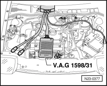
Connect adapter cable, 121-pin -V.A.G 1598/31- to control unit wiring harness.
–
Connect hand multimeter -V.A.G 1526C- to measure voltage between sockets 4/5 + 20 of adapter cable, 121-pin -V.A.G 1598/31-.
–
Switch on ignition.
–
Lift vehicle at front left.
–
Rotate front wheel and observe voltage display. Specification: between 0 and at least 10 Volt fluctuating
 Note
Note WARNING