volkswagen Workshop Repair Guides

Volkswagen Workshop Service and Repair Manuals

Checking components and functions > < Removing and installing O-rings for unit injector
Removing and installing unit injector
   
Removing and installing unit injector
Special tools and workshop equipment required
t  Universal dial gauge bracket -VW 387-
t  Special wrench, long reach -3410-
t  Special wrench, long reach -T10054-
t  Puller -T10055-
t  Torque wrench -V.A.G 1331-

  Note
   
Adjuster screw -1- and ball stud -2- of unit injector have been modified with the introduction of extended servicing intervals. Mixed installations are permissible for engines (older versions) without extended service intervals.
Removing
–  Remove upper toothed belt guard and cylinder head cover.
–  Turn crankshaft until the cam pair point evenly upwards for the unit injector which is to be removed.
  N23-0430
–  Loosen lock nuts of adjustment screws -1- and unscrew adjustment screws until the relevant rocker arm lies against the plunger springs of the unit injector.
–  Remove rocker arm securing bolts -2- (from outwards to inwards) with socket -3410- and take rocker arm shaft off.
–  Loosen tensioning block securing bolt -3- using special wrench, long reach -T10054- and remove tensioning block.
–  Lever connector off unit injector with a screwdriver. To avoid canting, support opposite side of connector with light finger pressure. Observe unit injector cylinder allocation.
  N23-0343
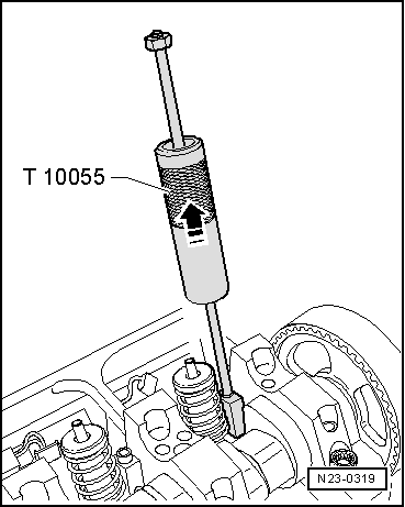
–  Insert puller -T10055- in the slot on the side of the unit injector in place of the clamping block.
–  Pull unit injector out of cylinder head seat with gentle taps.
Installing
  Note
t  
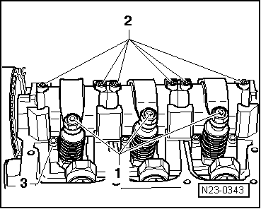
If a new unit injector is installed, the appropriate adjustment screw in the rocker arm must also be renewed.
t  Each time work is performed which requires the unit injector to be adjusted, the adjustment screw in the rocker arm and also the unit injector ball pin must be cleaned and checked for signs of wear. If wear is evident the ball pin and the adjustment screw must be renewed.
t  On older version of unit injector drive, lubricate contact surface between ball pin and adjustment screw with grease -G 000 100-.
t  
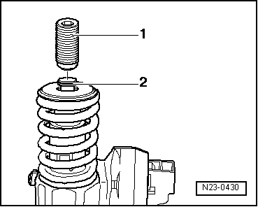
New unit injectors are supplied with O-rings and heat shield seal.
–  Heat shield seal and O-rings must be renewed if old unit injector is reused → Chapter.
–  Check that the three O-rings and the heat shield seal along with securing clip are seated correctly before installing unit injector.
  Note
The seals must not be twisted.
–  Oil the seals and fit the unit injector into the cylinder head with great care.
–  Push the unit injector evenly into the cylinder head onto its limit stop.
–  Insert the clamping block in the slot on the side of the unit injector.
  Note
If the unit injector is not at right angles to the tensioning block the securing bolt may loosen and this can damage the unit injector or the cylinder head.
–  Therefore align the unit injector as follows.
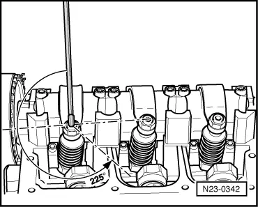
–  Screw the new securing bolt into the tensioning block only so far that the unit injector can still be turned easily.
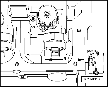
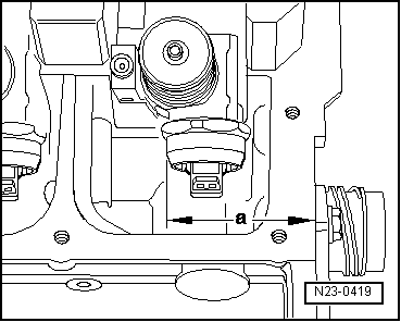
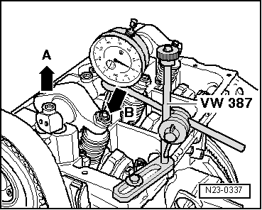
–  Now align unit injector at right angles to camshaft mounting brackets.
–  Check dimension “a” from outer edge of cylinder head to rounded edge of unit injector with a vernier gauge (measuring range at least 400 mm).
  Note
Gradual introduction of unit injector with new solenoid valve nut. A mixed installation is permissible providing measurement “a” is adhered to.
  N23-0319
Unit injector with old solenoid valve nut
  N23-0316
CylinderDimension “a”
1244.2 ± 0.8 mm
2156.2 ± 0.8 mm
364.8 ± 0.8 mm

   
Unit injector with new solenoid valve nut
  N23-0419
CylinderDimension “a”
1245.0 ± 0.8 mm
2157.0 ± 0.8 mm
365.6 ± 0.8 mm

Continuation for all unit injectors
–  Align unit injector and tighten securing bolt as follows: 12 Nm and turn 270° (3/4 turn) further (turning further can be done in several stages).
–  Fit the rocker arm shaft and tighten the new securing bolts as follows.
–  First tighten the inner and then both outer bolts hand tight evenly. Then using same sequence, tighten to 20 Nm and 90° (1/4 turn) further evenly.
   
–  Fit the dial gauge onto the adjustment screw of the unit injector as shown.
–  Turn the crankshaft in engine direction of rotation until the roller of the rocker arm is positioned on the peak of the drive cam. Roller side -arrow A- is at highest point, dial gauge -arrow B- is at lowest point.
–  Remove dial gauge.
–  Now turn adjustment screw into rocker arm until a firm resistance is felt (unit injector positioned at stop).
  N23-0337
–  Turn adjuster screw 225° back off stop.
–  Hold adjuster screw in this position and tighten lock nut to 30 Nm.
–  Push on unit injector connector and install cylinder head cover and toothed belt guard.
  N23-0342

Checking components and functions > < Removing and installing O-rings for unit injector