volkswagen Workshop Repair Guides

Volkswagen Workshop Service and Repair Manuals

Reworking valve seats > < Removing and installing camshaft housing
4-Cyl. injection engine (4 valve, roller rocker finger), Mechanics
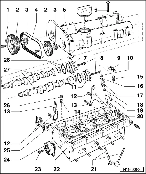
Servicing valve gear
 
N15-0082
  • 20 Nm + 1/4 turn (90 °) further
    • ◆ Renew
    • ◆ Use tool T 10016 to loosen and tighten , Fig.1
  • Camshaft sprocket
    • ◆ Note position when installing the toothed belt
  • Oil seal
    • ◆ Lightly oil sealing lip of oil seal
    • ◆ Renewing=> Page 15-40
  • Coupling drive toothed belt
    • ◆ Mark D.O.R. before removing
    • ◆ Check for wear
    • ◆ Do not kink
    • ◆ Removing and installing
      => Page 13-14
 
N15-0082
  • Camshaft housing
    • ◆ Removing and installing
      => Page 15-7
    • ◆ Remove sealant remnants
    • ◆ Coat with AMV 188 003 before fitting
    • ◆ When installing fit vertically from above onto studs and dowel pins
  • 10 Nm + 1/4 turn (90 °) further
    • ◆ Renew
    • ◆ Tighten from centre outwards
  • Sealing cap/ignition transformer retainer
  • 10 Nm
 
N15-0082
  • Roller rocker finger
    • ◆ Check roller bearing
    • ◆ Oil contact surface
    • ◆ Use securing clip to clip onto support element when installing
  • Cotters
  • Cap
  • 20 Nm
  • Lifting eye
  • Non-return valve, 6 Nm
    • ◆ Insert with D 154 102 A1
    • ◆ Do not overtighten, otherwise the valve can stick
  • Support element
    • ◆ Do not interchange
    • ◆ With hydraulic valve clearance compensation
    • ◆ Before installing check camshaft axial clearance => Page 15-35 , Fig. 3
    • ◆ Oil contact surface
 
N15-0082
  • Upper valve spring plate
  • Valve spring
    • ◆ Removing and installing:
      Cylinder head
      removed: with 3362
      installed: => Page 15-47 , Renewing valve stem seals
  • Valve stem seal
  • Service part - valve guide
    • ◆ With collar
  • Valve guide
  • Valves
    • ◆ Do not rework only grinding-in is permitted
    • ◆ Valve dimensions => Fig. 5
 
N15-0082
  • Cylinder head
    • ◆ Reworking valve seats
      => Page 15-37
    • ◆ Reworking sealing surface
      => Fig. 2
  • 20 Nm
  • Tensioner
    • ◆ Checking => Page 13-25
    • ◆ Tensioning toothed belts
      => Page 13-14
  • Retainer
  • Sealing plug, 45 Nm
    • ◆ Insert with D 154 102 A1
    • ◆ Must not be screwed in too far
    • ◆ Maximum permitted insertion depth from top of plug to camshaft housing surface = 2 mm
 
N15-0082
  • Camshafts
    • ◆ Checking axial clearance => Fig. 3
    • ◆ Identification and valve timing
      => Page 15-35 , Fig. 4
  • O-ring
    • ◆ Renew
    • ◆ Coat with oil before inserting
 
N13-0369

→ Fig. 1     Locking both camshaft sprockets with camshaft locking tool T 10016

  • ‒ Guide both locking pins through camshaft sprocket locking pin holes onto stop in camshaft housing fitting holes.

Note:

Both locking pins are inserted correctly when the ends -D- align with line -A-.

  • ‒ Slide retainer -B- onto stop on inlet camshaft sprocket -C-.
  • ‒ When both camshaft sprockets are locked in the fitting holes the camshaft pulleys can be loosened or tightened.
 
N15-0080

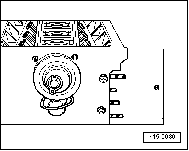
→ Fig. 2     Reworking cylinder head sealing surface

Cylinder head reworking dimension:
     a = At least 108.25 mm

Note:

When the sealing surface has been reworked, the valves must be set deeper by the same amount (rework valve seat inserts), otherwise valves will contact pistons. Ensure when doing this that the permissible minimum dimension is maintained => Page 15-37 .

 
N15-0087

→ Fig. 3     Checking camshaft axial clearance

Special tools, workshop equipment, testers, measuring instruments and auxiliary items required

  • ◆ VW 387 Universal dial gauge bracket
  • ◆ Dial gauge

Perform measurements with camshaft housing removed and sealing cover fitted.

Wear limit: max. 0.40 mm

 
N15-0090

→ Fig.4     Camshaft identification, valve timing

Identification

Identification between cam pairs

Cyl. 1 + 2

Cyl. 3

Inlet shaft -E-

"036AF"

"W2"

Exhaust shaft -A-

"036AG"

"W5"

Valve timing at 1 mm valve lift

Inlet opens after TDC

19.1 °

Inlet closes after BDC

15.1 °

Exhaust opens before BDC

20.2 °

Exhaust closes before TDC

15.3 °

 
V15-0024

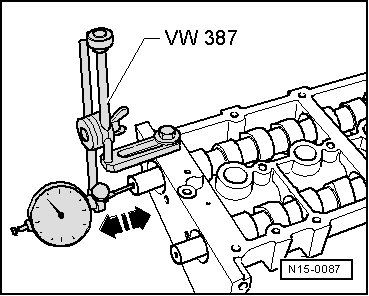
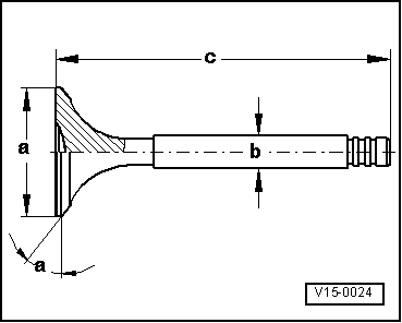
→ Fig. 5     Valve dimensions

Note:

Valves must not be reworked. Only lapping-in is permitted.

Dimension

Inlet valve

Exhaust valve

øa

mm

29.5

26.0

øb

mm

5.973

5.953

c

mm

100.9

100.5

α

45

45

Reworking valve seats > < Removing and installing camshaft housing