| –
| If no realistic display appears in display zone 1 or a substitute temperature of -5.4°C is displayed, check fuel temperature sender -G81- and line connections to sender as follows: |
| –
| Press buttons 0 and 6 for function “End data transfer” and confirm entry with Q button. |
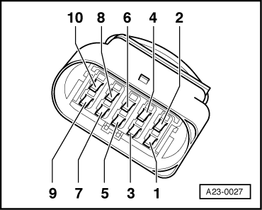
| Engine code AGD (with 68-pin control unit) |
|
|
Read measured value block 7 -> | 15.4°C 15.9°C 16.7°C |
|