In the event of a fault message, fault reader -V.A.G 1551- display shows fault code 00527 for intake manifold temperature sender-G72-.
Special tools and workshop equipment required
t
Fault reader -V.A.G 1551- or vehicle system tester -V.A.G 1552- with diagnosis cable -V.A.G 1551/3-
t
Adapter cable (68-pin) -V.A.G 1598/18A- or adapter -V.A.G 1598/22-
t
Hand multimeter -V.A.G 1526C- or multimeter -V.A.G 1715-
t
Auxiliary measuring set -V.A.G 1594C-
t
Current flow diagram
Test procedure
–
Connect fault reader -V.A.G 1551- or vehicle system tester -V.A.G 1552- and select engine electronics control unit with “address word 01”. Engine must be idling. (Connect fault reader -V.A.G 1551- and select engine electronics control unit → Chapter.)
Indicated on display:
–
Press buttons 0 and 8 for function “Read measured value block” and confirm entry with Q button.
Rapid data transfer HELP
Select function XX
Indicated on display:
–
Press buttons 0, 0 and 7 for “Display group number 7” and confirm entry with Q button.
Read measured value block HELP
Input display group number XXX
Indicated on display:
–
If no realistic display appears in display zone 3 or a substitute temperature of 136.8°C is displayed, check intake air temperature sender -G42- and line connections to sender as follows:
–
Press → button.
–
Press buttons 0 and 6 for function “End data transfer” and confirm entry with Q button.
–
Switch off ignition.
Read measured value block 7 ->
15.4°C 15.9°C 16.7°C
–
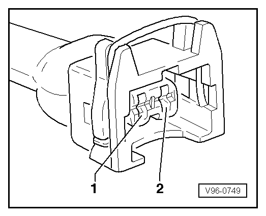
Remove connector from intake air temperature sender -G42--arrow-.
–
Measure resistance between sender contacts.
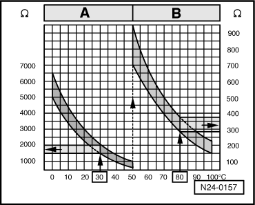
Specification see diagram.
Scale A shows resistance values for temperature range 0..50°C and scale B the values for temperature range 50..100°C.
Examples:
t
30 °C corresponds to a resistance of 1500..2000 Ω
t
80 °C corresponds to a resistance of 275..375 Ω
If the specification is not achieved:
–
Renew intake air temperature sender -G42-.
If the specification is attained:
Engine code AGD (with 68-pin control unit)
–
Connect adapter cable, 68-pin -V.A.G 1598/18A- to control unit wiring harness.
–
Check lines between adapter cable (68-pin) -V.A.G 1598/18A- and connector for open circuit according to current flow diagram. Contact 1 + socket 64 Contact 2 + socket 33.
Cable resistance: max. 1.5 Ω.
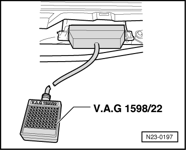
Engine codes AGD (with 80-pin control unit), AHG, AKU
–
Connect adapter -V.A.G 1598/22- to control unit wiring harness.
–
Check lines between adapter -V.A.G 1598/22- and connector for open circuit according to current flow diagram. Contact 1 + socket 13 Contact 2 + socket 25.
Cable resistance: max. 1.5 Ω.
Continuation for all engine codes
–
Also check wiring for short to one another, short to vehicle earth and short to battery positive.
Specification: ∞ Ω.
If no fault in lines is detected:
–
Renew diesel direct injection system control unit -J248- → Chapter.
 Note
Note