volkswagen Workshop Repair Guides

Volkswagen Workshop Service and Repair Manuals

Checking accelerator position sender G79 > < Checking exhaust gas recirculation valve N18 voltage supply
Checking speedometer senderG22
Checking speedometer sender -G22-
Special tools and workshop equipment required
t  Fault reader -V.A.G 1551- or vehicle system tester -V.A.G 1552- with diagnosis cable -V.A.G 1551/3-
t  Adapter cable (68-pin) -V.A.G 1598/18A- or adapter -V.A.G 1598/22-
t  Hand multimeter -V.A.G 1526C- or multimeter -V.A.G 1715-
t  Voltage tester -V.A.G 1527B-
t  Auxiliary measuring set -V.A.G 1594C-
t  Current flow diagram
Test prerequisite
l  Speedometer OK., checking → Electrical System; Rep. Gr.90
  Note
To check the speed signal the vehicle must be driven. To do this a second person is necessary.
  WARNING
Secure fault reader to rear seat and operate from this position.
Test procedure
–  Connect fault reader -V.A.G 1551- or vehicle system tester -V.A.G 1552- and select engine electronics control unit with “address word 01”. Engine must be idling. (Connect fault reader -V.A.G 1551- and select engine electronics control unit → Chapter.)
   
Indicated on display:
–  Press buttons 0 and 8 for function “Read measured value block” and confirm entry with Q button.
 
Rapid data transfer                 HELP
Select function XX                    
Indicated on display:
–  Press buttons 0, 0 and 6 for “Display group number 6” and confirm entry with Q button.
–  Carry out a road test and compare display with speedometer (2nd person required).
 
Read measured value block           HELP
Input display group number XXX       
Specification display zone 1: Approx. road speed.
–  Press button.
–  Press buttonss 0 and 6 for function “End output” and confirm entry with Q button.
If no speed is indicated:
Engine code AGD (with 68-pin control unit)
 
Read measured value block 6           ->
    0 km/h     0  0  0    000000     255
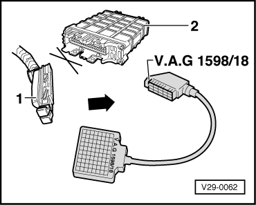
–  Connect adapter cable, 68-pin -V.A.G 1598/18A- to control unit wiring harness.
–  Bridge sockets 1+42 with auxiliary lines from-V.A.G 1594-.
–  Set voltage measuring range on hand-held multimeter -V.A.G 1526C- or multimeter -V.A.G 1715- and connect between sockets 43 + 33 of adapter cable (68-pin) -V.A.G 1598/18A-.
–  Switch on ignition.
–  Raise and rotate left front wheel.
Specification:
Between 0 and 5 volt fluctuating
  Note
If necessary, hold the front right wheel to prevent it from turning.
If the display does not fluctuate:
–  Check lines to speedometer/speedometer sender → Current flow diagrams, Electrical fault finding and Fitting locations
Engine codes AGD (with 80-pin control unit), AHG, AKU
  V29-0062
–  Connect adapter -V.A.G 1598/22- to control unit wiring harness.
–  Connect voltage tester -V.A.G 1527B- between socket 1 (ground) and socket 51 (speed signal).
–  Switch on the ignition and turn the front left wheel by hand.
  Note
If necessary, hold the front right wheel to prevent it from turning.
–  The voltage tester -V.A.G 1527B- must flash (approx. four times per wheel rotation).
–  If the voltage tester -V.A.G 1527B- does not flash, check line connection from engine control unit connector contact 51 to dash panel insert for open/short circuit. → Current flow diagrams, Electrical fault finding and Fitting locations
  N23-0197

Checking accelerator position sender G79 > < Checking exhaust gas recirculation valve N18 voltage supply