volkswagen Workshop Repair Guides

Volkswagen Workshop Service and Repair Manuals

Checking signal from clutch pedal switch F36 . > < Checking speed signal
Checking signal from brake light switchF and brake pedal switchF47.
Checking signal from brake light switch -F- and brake pedal switch -F47-.
Function
Because the injection system operates with an accelerator pedal sender (potentiometer) which may be defective, the engine is regulated for reasons of safety when the brakes are operated. To do this the control unit requires signals from the brake light switch and also the brake pedal switch. This means that if the brakes are operated when the accelerator pedal is held at a constant position the engine is immediately reduced to idling speed. Incorrectly adjusted switches may lead to unrequired regulating action
Special tools and workshop equipment required
t  Hand multimeter -V.A.G 1526C- or multimeter -V.A.G 1715-
t  Fault reader -V.A.G 1551- or vehicle system tester -V.A.G 1552- with diagnosis cable -V.A.G 1551/3-
t  Adapter set -V.A.G 1594C-
t  Adapter cable, 121-pin -V.A.G 1598/31-
t  Current flow diagram
Test prerequisites
   
l  Fuses must be OK.
l  The battery voltage must be at least 11.5 V.
Test procedure
–  Connect fault reader -V.A.G 1551- or vehicle system tester -V.A.G 1552- and select engine electronics control unit with “address word 01”. The ignition must be switched on for this purpose. (Connecting fault reader -V.A.G 1551- and selecting engine electronics control unit → Chapter).
  N24-0831
Indicated on display:
–  Press keys 0 and 8 for function “Read measured value block” and confirm entry with Q key.
 
Rapid data transfer                 HELP
Select function XX                    
Indicated on display:
–  Press keys 0, 0 and 6 for “Display group number 6” and confirm entry with Q key.
–  Observe display in display zone 2.
 
Read measured value block                     
Input display group number XXX       
Specification: 0 0 0
t  Middle display = brake pedal switch -F47-.
t  Right display = brake light switch -F-.
–  Operate brake pedal slowly. Both displays must simultaneously switch from 0 to 1.
 
Read measured value block 6          ->
    0 km/h     0  0  0    000000    255
Specification: 0 1 1
–  Release brake pedal slowly into rest position again.
 
Read measured value block 6                 ->
    0 km/h     0  1  1    000000    255
Both displays must change from 1 to 0 again.
–  Press key.
–  Press keys 0 and 6 for function “End output” and confirm entry with Q key.
–  Switch off ignition.
If one or both displays do not change:
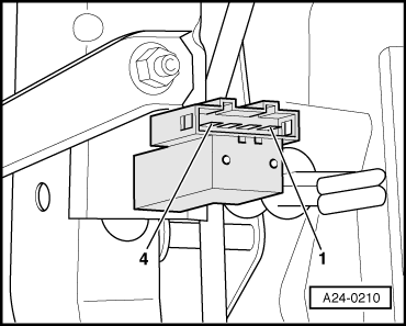
–  Remove cover in footwell (driver side).
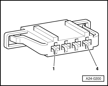
–  Pull 4-pin connector off brake light switch -F- and brake pedal switch -F47-.
 
Read measured value block 6          ->
    0 km/h     0  0  0    000000    255
–  Measure resistance between switch contacts 1 + 4.
Specification: Brake not depressed: ∞ Ω∼(no continuity), brake depressed: Max. 1.5 Ω
–  Measure resistance between switch contacts 2 + 3.
Specification: Brake not depressed: Max. 1.5 Ω, brake depressed: ∞ Ω∼(no continuity)
If the specifications are not attained:
–  Renew brake light switch -F- and brake pedal switch -F47-.
If the specifications are attained:
  A24-0210
–  Connect adapter cable, 121-pin -V.A.G 1598/31- to control unit wiring harness. The engine control unit remains disconnected.
  N01-0369
–  Check wiring between 121-pin adapter cable -V.A.G 1598/31- and 4-pin connector for open circuit according to current flow diagram. Contact 2 + socket 1 Contact 2 + socket 2 Contact 3 + socket 65 Contact 4 + socket 32.
Cable resistance: max. 1.5 Ω.
–  Check the line between 4-pin connector contact 1 and central electrics according to current flow diagram: → Current flow diagrams, Electrical fault finding and Fitting locations
–  Also check wiring for short to one another, short to vehicle earth and short to battery positive.
Specification: ∞ Ω.
If no fault in lines is detected:
–  Renew engine control unit → Chapter.
  A24-0200

Checking signal from clutch pedal switch F36 . > < Checking speed signal