volkswagen Workshop Repair Guides

Volkswagen Workshop Service and Repair Manuals

Checking intake air temperature sender > < Checking throttle valve control part
Simos injection and ignition system
Checking components
Checking intake manifold pressure sender

Note:

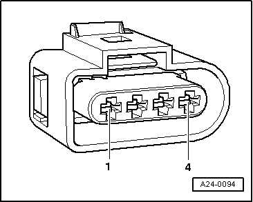
Only gold-plated contacts may be used when servicing the sender connector contacts

Special tools, workshop equipment, testers, measuring instruments and auxiliary items required

  • ◆ Hand multimeter V.A.G 1526 or multimeter V.A.G 1715
  • ◆ Adapter set V.A.G 1594
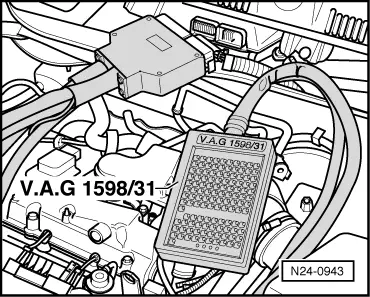
  • ◆ Test box V.A.G 1598/31
  • ◆ Current flow diagram
 
N24-0943

Test sequence

  • ‒ → Connect test box V.A.G 1598/31 to control unit wiring harness. The engine control unit remains disconnected.
 
N24-0910
  • ‒ → Pull 4-pin connector off intake manifold pressure sender (G71) and intake air temperature sender (G42) -arrow-.
 
A24-0094
  • ‒ → Check wiring for open circuit between test box and 4-pin connector referring to current flow diagram:
         Contact 3 and test box socket 96
         Contact 4 and test box socket 95
         Wire resistance: max. 1.5 ω
  • ‒ Additionally check wires for short to one another, to vehicle earth and to battery positive.
         Specification: ∞ω

If no fault is detected in the wiring:

  • ‒ Remove air cleaner , Fig. 2 .
  • ‒ Renew the intake manifold pressure sender (G71) with intake air temperature sender (G42)
    => Page 24-17 , item 2 .
  • ‒ Interrogate fault memory, if necessary, repair any faults and then erase fault memory => Page 01-20 , interrogating and erasing fault memory.
  • ‒ Erase the learnt values and adapt the engine control unit again=> Page 24-128 .

Checking intake air temperature sender > < Checking throttle valve control part