volkswagen Workshop Repair Guides

Volkswagen Workshop Service and Repair Manuals

Checking intake manifold pressure sender > < Checking Lambda probe heating for Lambda probe after catalyst
Simos injection and ignition system
Checking components
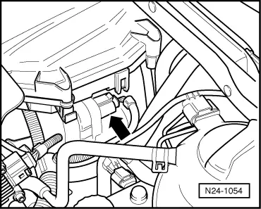
Checking throttle valve control part

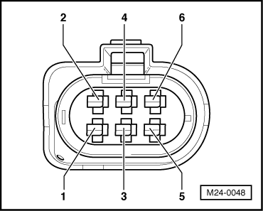
Components of throttle valve control part (J338):
Throttle valve drive (G186), angle sender 1 for throttle valve drive (G187) and angle sender 2 for throttle valve drive (G188).

Notes:

  • ◆ Only gold-plated contacts may be used when servicing the throttle valve control part connector contacts.

If the throttle valve control part is replaced, the following must be carried out:

  • ◆ Erase learnt values and adapt engine control unit to the throttle valve control part .

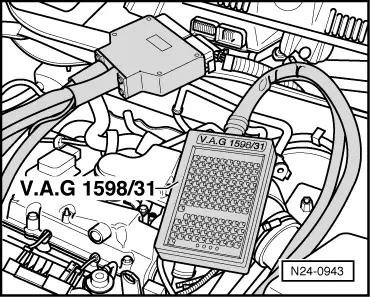
Special tools, workshop equipment, testers, measuring instruments and auxiliary items required

  • ◆ Hand multimeter V.A.G 1526 or multimeter V.A.G 1715
  • ◆ Fault reader V.A.G 1551 (or vehicle system tester V.A.G 1552) with cable V.A.G 1551/3
  • ◆ Adapter set V.A.G 1594
  • ◆ Test box V.A.G 1598/31
  • ◆ Current flow diagram

Check conditions

  • ● The battery voltage must be at least 11.5 V.
  • ● All electrical consumers, e.g. lights and rear window heating must be switched off.
  • ● If the vehicle is equipped with an air conditioning system, this must be switched off.
  • ● Coolant temperature must be at least 80 °C, =>display group 04, display zone 3.

Test sequence

  • ‒ Connect the fault reader V.A.G 1551 (V.A.G 1552). Then switch ignition on and select engine control unit with the "Address word" 01.
    (Connecting fault reader and selecting engine control unit => Page 01-10 .)
 
→ Indicated on display:
Rapid data transfer     HELP
Select function XXX
  • ‒ Press keys 0 and 8 for the function "Read measured value block" and confirm entry with Q key.
 
→ Indicated on display:
Read measured value block
Input display group number XXX
  • ‒ Press keys 0, 6 and 2 for the "Display group number 62" and confirm entry with Q key.
 
→ Indicated on display:
(1...4 = Display zones)
Read measured value block 62     ⇒
     1     2     3     4
  • ‒ Check throttle valve angle sender 1 (G187) at idling speed limit stop in display zone 1
         Specification: 0.0...100.0 %
  • ‒ Check throttle valve angle sender 2 (G188) at idling speed limit stop in display zone 2
         Specification: 100.0...0.0 %
  • ‒ Depress accelerator slowly to full throttle position and observe angles displayed in display zones 1 and 2:
  • The percentage in display zone 1 must rise
         evenly.
    The tolerance range 0.0...100.0 % is never used completely.
  • The percentage in display zone 2 must fall
         evenly.
    The tolerance range 100.0...0.0 % is never used completely.

Notes:

  • ◆ The reason why the display in display zone 1 increases and the display in display zone 2 decreases is because the potentiometers (angle senders) in the throttle valve control part run in opposite directions.
  • ◆ This means that the voltage of one angle sender moves towards 5 volts. (The more the throttle valve is opened the higher the voltage; percentage figure increases).
  • ◆ Whilst the voltage of angle sender 2 decreases from 5 volts towards 0 volts. (The more the throttle valve is opened the lower the voltage; percentage figure decreases).
  • ‒ Press ⇒key.
  • ‒ Press keys 0 and 6 for the function "End output" and confirm entry with the Q key.
  • ‒ Switch off ignition.

If the displays do not indicate as described:

  • ‒ Remove air cleaner => Page 24-26 , Fig. 2 .
 
N24-1054
  • ‒ → Pull 6-pin connector off throttle valve control part -arrow-.
 
N24-1092
  • ‒ → Measure the resistance on throttle valve control part between the contacts 3 + 5
         Specification: 1.0...5.0 ω(at room temperature)

If the specification is not obtained:

  • ‒ Replace throttle valve control part
    => Page 24-18 , item 7 .
  • ‒ Interrogate fault memory, if necessary, repair any faults and then erase fault memory => Page 01-20 , interrogating and erasing fault memory.
  • ‒ Erase the learnt values and adapt the engine control unit again=> Page 24-128 .

If the specification is obtained:

  • ‒ Check voltage supply of throttle valve control part and wiring to control unit => Page 24-47 .
  • ‒ Check the accelerator pedal position sender.

=> Repair group 20; Electronic engine output regulation (electronic accelerator (EPC)); Checking accelerator pedal position sender

If the voltage supply and wiring is OK:

  • ‒ Replace engine control unit
    => Page 24-121 .

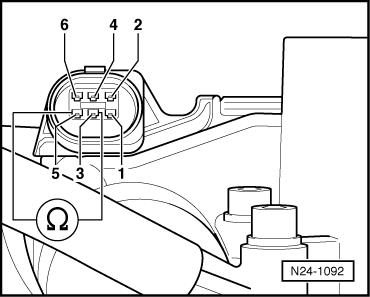
Checking voltage supply and wiring to control unit

 
M24-0068
  • ‒ → Connect multimeter to measure voltage at connector contacts 2 (positive) + 6 (earth).
  • ‒ Switch on ignition.
         Specification: min. 4.5 V
  • ‒ Switch off ignition.
 
M24-0069
  • ‒ → Connect multimeter to measure voltage at connector contact 2 (positive) and earth.
  • ‒ Switch on ignition.
         Specification: min. 4.5 V
  • ‒ Switch off ignition.

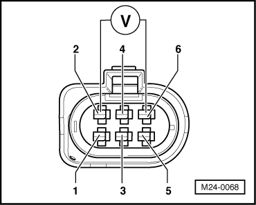
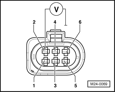
If the specifications are not attained:

 
N24-0943
  • ‒ → Connect test box V.A.G 1598/31 to control unit wiring harness. The engine control unit remains disconnected.
 
M24-0048
  • ‒ → Check wiring for open circuit between test box and connector referring to current flow diagram:
         Contact 1 and test box socket 90
         Contact 2 and test box socket 97
         Contact 3 and test box socket119
         Contact 4 and test box socket 92
         Contact 5 and test box socket121
         Contact 6 and test box socket 91
         Wire resistance: max. 1.5 ω
  • ‒ Additionally check wires for short to one another, to vehicle earth and to battery positive.
         Specification: ∞ω

If no fault is detected in the wiring:

  • ‒ Check engine control unit voltage supply => Page 24-117 .

Checking intake manifold pressure sender > < Checking Lambda probe heating for Lambda probe after catalyst