Polo Mk3
|
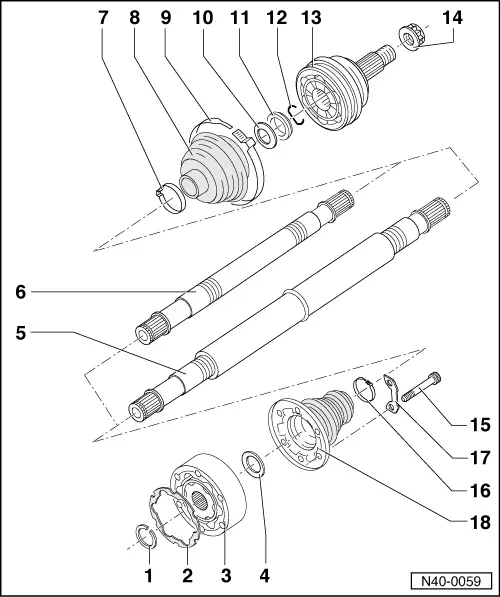
Servicing drive shaft
Assembly overview drive shaft with constant velocity joint
|
 |
|
|
|
|
|
|
|
|
 |
|
|
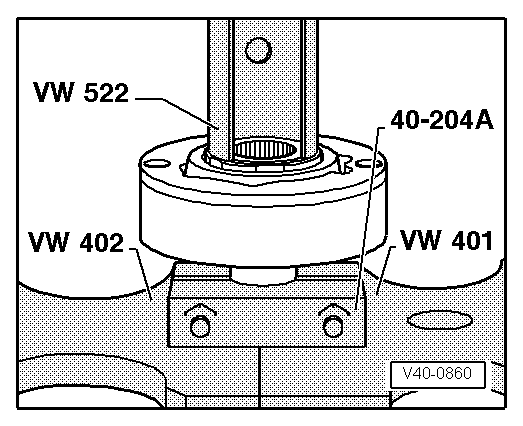
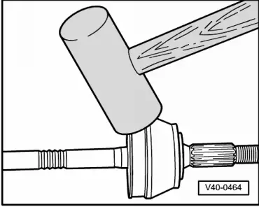
→ Fig.1 Removing outer constant velocity joint
|
 |
|
|
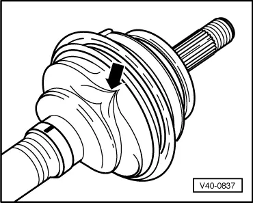
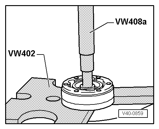
→ Fig.2 Pressing off inner constant velocity joint Notes:
|