volkswagen Workshop Repair Guides

Volkswagen Workshop Service and Repair Manuals

Removing and installing radio/navigation system > < Electronic anti-theft system
Radio, telephone, navigation
Radio navigation system (RNS)
Connections on radio navigation system
 
N91-0201
  • Navigation system aerial connection
  • Multi-pin connection I
    • ◆ 20-pin connection for DSP, pre-amplifier output, telephone speech input and second display as well as CD changer control
    • ◆ Pin assignment =>page 91-75
  • Multi-pin connection II
    • ◆ 8-pin connection for loudspeaker output
    • ◆ Pin assignment =>page 91-76
 
N91-0201
  • Multi-pin connection III
    • ◆ 8-pin connection for supply voltage, telephone mute, GALA signal, illumination, "Safe" locking and S contact
    • ◆ Pin assignment =>page 91-77
  • Multi-pin connection IV
    • ◆ 10-pin connection for navigation sensors
    • ◆ Pin assignment =>page 91-78
  • Radio aerial connection

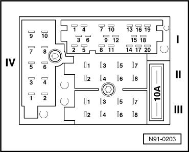
Pin assignment for multi-pin connection I

Multi-pin connector I, -T20- consists of 3 parts that are marked with different colours:

 
N91-0203

→ Multi-pin connector I, part 1, yellow

  •      1 -     Vacant
  •      2 -     Vacant
  •      3 -     Line Out, earth
  •      4 -     Line Out front left, LF
  •      5 -     Line Out front right, RF
  •      6 -     Switched positive for sound amplifier

Multi-pin connector I, part 2, green

  •      7 -     Telephone input signal, TEL+
  •      8 -     Second display, CLOCK (precondition for data flow pulse frequency)
  •      9 -     Second display, DATA (exchange of data for dash panel insert with second display)
  •      10 -     Second display, ENA (monitoring of data flow and feedback of successful data transfer)
  •      11 -     Remote control
  •      12 -     Telephone input signal, TEL-
 
N91-0203

→ Multi-pin connector I, part 3, blue

  •      13 -     CD changer, DATA IN (data to radio)
  •      14 -     CD changer, DATA OUT (data from radio)
  •      15 -     CD changer, CLOCK (precondition for data flow pulse frequency)
  •      16 -     CD changer, terminal 30 voltage supply (+)
  •      17 -     CD changer, control signal
  •      18 -     CD changer, left and right channel, earth
  •      19 -     CD changer, left channel, CD/L
  •      20 -     CD changer, right channel, CD/R

Pin assignment for multi-pin connection II

Multi-pin connector II, -T8a-, 8-pin, brown

  •      1 -     Loudspeaker + rear right
  •      2 -     Loudspeaker - rear right
  •      3 -     Loudspeaker + front right
  •      4 -     Loudspeaker - front right
  •      5 -     Loudspeaker + front left
  •      6 -     Loudspeaker - front left
  •      7 -     Loudspeaker + rear left
  •      8 -     Loudspeaker - rear left
 
N91-0203

Pin assignment for multi-pin connection III

→ Multi-pin connector III, -T8-, 8-pin, black

  •      1 -     Gala (volume adaption)
  •      2 -     Telephone mute circuit
  •      3 -     Self-diagnosis/K wire
  •      4 -     Connection for ignition key controlled switching on and off (S contact)
  •      5 -     Anti-theft system control signal, SAFE
  •      6 -     Illumination (terminal 58b)
  •      7 -     Battery + (terminal 30)
  •      8 -     Battery - (terminal 31)

Pin assignment for multi-pin connection IV

 
N91-0203

→ Multi-pin connection IV, -T10-, 10-pin, red

  •      1 -     CAN bus earth for DSP system
  •      2 -     Speech earth (instructions)
  •      3 -     CAN bus low for DSP system
  •      4 -     Speech NF positive (instructions)
  •      5 -     CAN bus high for DSP system
  •      6 -     Speech NF negative (instructions)
  •      7 -     Vacant (option with telematics)
  •      8 -     Ignition (terminal 15)
  •      9 -     Vacant (option with telematics)
  •      10 -     Signal reverse gear

Removing and installing radio/navigation system > < Electronic anti-theft system