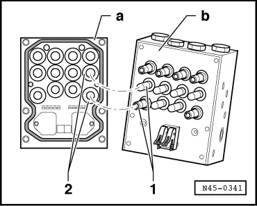
While installing the command device -a- on the hydraulic unit -b-, ensure that the valve tubes -1- are not bent with the electromagnetic coils -2-.
–
Install the command device to the hydraulic unit.
–
Press the command device on the hydraulic system seating surface until it fits completely with the hydraulic unit rib and remains in this position.
–
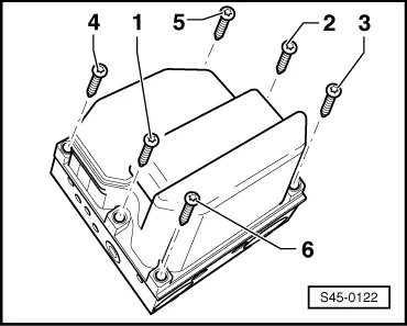
Alternately tighten the central screws -1- and -2-, until the command device is fastened to the hydraulic unit.
Use the new Torx screws provided with the set.
–
Install screws -3- to -6- and tighten the screws until the command device is fully seated.
–
Then, alternately tighten the crews.
–
Tighten the screws in the sequence from -1- to -6- to 3 Nm.
The hydraulic unit threads used to fasten the command device must not be damaged. If the thread is damaged (trouble in tightening the screws manually or screws not tightened to the specified torque), replace the hydraulic system unit.
–
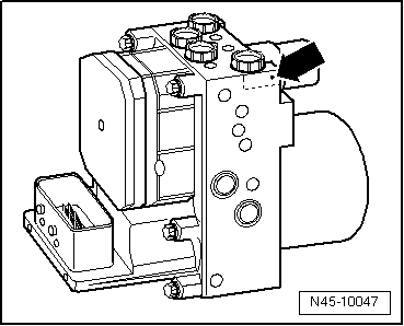
Identify with a punch, in the traced area -arrow-, each assembly of the hydraulic unit with a command device.
Note
The hydraulic unit supports only 5 assemblies in the command unit. After 5 assemblies in the command unit, it must be replaced.
 Note
Note