volkswagen Workshop Repair Guides

VW Polo Workshop Service and Repair Manuals

F - Re-pressing sender wheel > < D-Pressing sender wheel onto crankshaft flange with assembly appliance T10017
E - Checking sender wheel installation position on crankshaft
   
–  Screw hexagon nut -A- to end of threaded spindle.
–  Remove the two M6×35 mm hexagon bolts -B- from cylinder block.
–  Screw the three thumb wheels -C- out of sealing flange.
–  Pull assembly appliance assembly bell housing -D- back to hexagon nut -A- (Only for sealing flange with spring ring).
  N13-0421
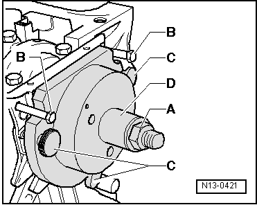
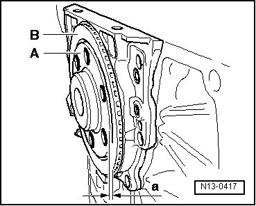
The sender wheel is in the correct installation position on the crankshaft if a gap -a- = 0.5 mm exists between crankshaft flange -A- and sender wheel -B-.
  Note
t  If the sealing flange has a PTFE sealing ring, completely unbolt the assembly appliance -T10017- and remove the sealing lip support ring.
t  To enable dimension -a- to be shown more clearly the crankshaft flange is illustrated without fitted assembly appliance -T10017-.
  N13-0417
–  Place a vernier caliper against the crankshaft flange -A- (hatched area).
  N13-0418
–  Measure the distance -a- between vernier caliper and sender wheel with a feeler gauge -A-.
If measurement -a- too small:
–  Re-press sender wheel → Chapter.
When dimension -a- is achieved:
–  Remove assembly appliance.
–  Tighten the new securing bolts for the sealing flange using alternate and diagonal sequence. Torque setting: 12 Nm.
  N13-0419
–  Install engine speed sender -arrow-. Torque setting: 5 Nm.
–  Install oil sump → Chapter.
–  Install intermediate plate.
–  Install flywheel/drive plate with new bolts.
  N13-0380

F - Re-pressing sender wheel > < D-Pressing sender wheel onto crankshaft flange with assembly appliance T10017