
Polo Mk4
| Pistons and rods - disassemble and assemble |

| 1 - | Guide rings |
| q | Displace opening 120° |
| q | Remove and install with ring plier |
| q | Reference “TOP” turned to piston head |
| q | Check intergate openings → Fig. |
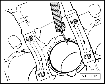
| q | Check ring space on piston channel → Fig. |
| 2 - | Piston |
| q | With combustion chamber |
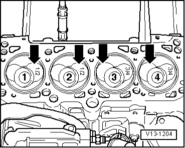
| q | Mark installation position and cylinder correspondence |
| q | Piston/cylinder installation position → Fig. |
| q | -Arrow- on piston head points to belt pulley side |
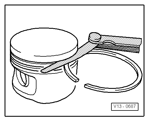
| q | Install with ring tension belt |
| q | If piston is cracked, replace it |
| q | Check piston position on upper part → Chapter. |
| 3 - | Piston pin |
| q | If piston is locked, heat at 60 °C |
| q | Remove and install with Drift -VW 222A- |
| 4 - | Lock |
| 5 - | Rod |
| q | Replace only set |
| q | Mark cylinder position -A- |
| q | Installation position: Markings -B- point to belt pulley side |
| 6 - | Adjusting pin |
| q | Adjusting pin must be firmly positioned on rod |
| 7 - | Cap |
| q | Mind installation position |
| q | Do not change used caps position |
| q | Mind proper seating on retaining protuberances |
| q | Axial space wear limit: 0.37 mm. |
| q | Measure radial space with “Plastigage”: wear limit: 0.08 mm. During radial space measurement, do not move crankshaft |
| 8 - | Engine block |
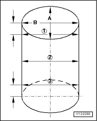
| q | Check cylinder diameter → Fig. |
| q | Piston and cylinder measures → Chapter. |
| 9 - | Rod cover |
| q | Mind installation position |
| 10 - | Oil ejector |
| q | For piston cooling |
| 11 - | 25 Nm |
| q | Install without seal |
| 12 - | Rod screw, 30 Nm + 90 |
| q | Replace |
| q | Oil thread and support surface |
| q | For radial space measurement, use used screw |
| Segment ring measures in mm | new | Wear limit |
| 1. Compression ring | 0.25...0.40 | 1.0 |
| 2. Compression ring | 0.20...0.40 | 1.0 |
| Oil scraper ring | 0.25...0.50 | 1.0 |
|
|
| Segment ring measures in mm | new | Wear limit |
| 1. Compression ring | 0.06...0.09 | 0.25 |
| 2. Compression ring | 0.05...0.08 | 0.25 |
| Oil scraper ring | 0.03...0.06 | 0.15 |
 Note
Note
|
|
Note
|
|