Polo Mk4
 Note
Note
|
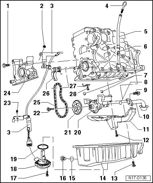
| 1 - | 15 Nm |
| 2 - | 25 Nm |
| 3 - | Support |
| q | Level sensor wiring harness-/oil temperature. |
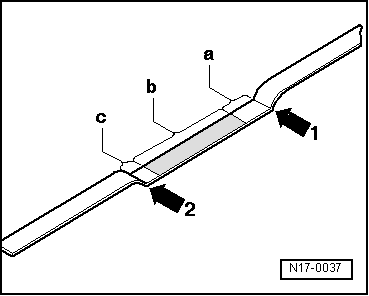
| 4 - | Oil level measuring stick |
| q | Oil level must not be over the max. marking! |
| q | Markings → Fig., → Fig. |
| 5 - | Stick tube |
| q | Remove to suck oil |
| 6 - | Guide tube |
| 7 - | Guide bushing |
| 8 - | Sealing ring |
| q | Replace |
| 9 - | 15 Nm |
| 10 - | Suction tube |
| q | Clean sieve if dirty |
| 11 - | Anti-shake board |
| 12 - | 15 Nm |
| 13 - | 15 Nm |
| 14 - | Oil carter |
| q | Clean sealing surface before assembly |
| q | Assemble with silicone seal -D 176 404 A2- → Chapter. |
| 15 - | Sealing ring |
| q | Replace |
| 16 - | Oil draining plug 30 Nm |
| 17 - | 10 Nm |
| 18 - | Oil level and temperature sensor -G266- |
| q | Black 3-pin linking connector |
| q | Check: → Electric systems folder, fault location with VAS 5051 |
| 19 - | Sealing ring |
| q | Replace |
| 20 - | Oil pump |
| q | With 12 bar over-pressure valve |
| q | Before installation, check if both guide-bushings for oil pump/engine block centralization are in place |
| q | Replace in case fluting is formed on the sliding surfaces and on gears |
| 21 - | Oil pump chain gear |
| 22 - | 25 Nm |
| 23 - | 15 Nm |
| 24 - | Sealing flange |
| q | With sealing ring |
| q | Must seat on guide-pins |
| q | Remove and install → Chapter. |
| q | Assemble with silicone seal -D 176 404 A2- → Chapter. |
| q | Do not lubricate sealing lip of seal |
| q | Before installation, remove oil residues on crankshaft neck with a clean cloth |
| q | Crankshaft sealing ring -pulley side- replace → Chapter and → Chapter. |
| 25 - | Chain |
| 26 - | Chain strainer with tightening rail, 15 Nm |
| q | When installing, pre-tighten spring and hook |
| 27 - | Oil ejector |
| q | For piston refrigeration |
| 28 - | 25 Nm |
| q | Assemble without sealing |
|
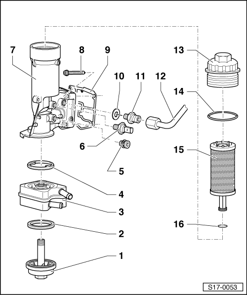
| 1 - | Threaded plug, 25 Nm |
| 2 - | Joint |
| q | Replace |
| 3 - | Oil radiator |
| q | Mind the free space between adjacent components |
| q | Mind the note → Chapter. |
| 4 - | Joint |
| q | Replace |
| 5 - | Threaded plug, 10 Nm |
| q | In case of leakage, cut sealing ring and replace it |
| 6 - | Oil pressure switch -F1-, 20 Nm |
| q | 0.7 bar switch: brown or 0.9 bar switch: gray |
| q | In case of leakage, cut sealing ring and replace it |
| q | Check → Chapter. |
| 7 - | Oil filter support |
| 8 - | 15 Nm + 90 ° |
| q | Replace |
| q | First seat screw on top left and below right, then tighten 4 screws in cross |
| 9 - | Joint |
| q | Replace |
| 10 - | Sealing ring |
| q | Replace |
| 11 - | Connection flange 35 Nm |
| 12 - | Oil supply tube |
| q | To the turbo-compressor |
| 13 - | Draining plug, 25 Nm |
| q | Loosen and tighten with oil filter wrench 3417 |
| 14 - | Sealing ring |
| q | Replace |
| 15 - | Oil filter placement |
| q | Observe installation position: top = top |
| 16 - | Sealing ring |
| q | Replace |