
Polo Mk4
 Note
Note
|
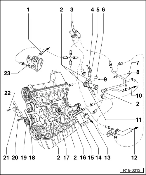
| 1 - | To the coolant reservoir |
| 2 - | Sealing ring |
| q | Replace. |
| 3 - | Heat exchanger connections |
| 4 - | Coolant temperature sensor -G62- coupling connector |
| q | With 2-pole. |
| 5 - | Coolant temperature sensor -G62- |
| q | For the Engine control unit -J623-. |
| q | If necessary, depressurize the cooling system prior to removal. |
| 6 - | Clip |
| q | Check firm fitting. |
| 7 - | 25 Nm |
| 8 - | Cooling system tube |
| 9 - | 10 Nm |
| 10 - | Below the coolant reservoir |
| 11 - | Connection nozzle |
| 12 - | Above the radiator |
| 13 - | Below the radiator |
| 14 - | Oil radiator |
| q | Pay attention to the free space in relation to the adjacent components. |
| q | Pay attention to the note → Chapter. |
| 15 - | 15 Nm |
| 16 - | Connection nozzle |
| 17 - | Thermostat valve for the cooling system |
| q | Check: heat the thermostat in double boiler. |
| q | Opening start with approx. 87° C. |
| q | Minimum opening travel 7 mm. |
| q | Remove and install → Chapter. |
| 18 - | Timing belt |
| q | Mark the rotation direction before removing. |
| q | Check wear. |
| q | Do not bend. |
| q | Remove and install, adjust → Chapter. |
| 19 - | Water pump |
| q | Check mobility. |
| q | In case of damage and leaks, replace in its entirety. |
| q | Remove and install → Chapter. |
| 20 - | 15 Nm |
| 21 - | Mechanical distribution rear cover |
| 22 - | 20 Nm |
| 23 - | Throttle butterfly valve control unit -J338- |
| q | Heated by the coolant. |