
Polo Mk4
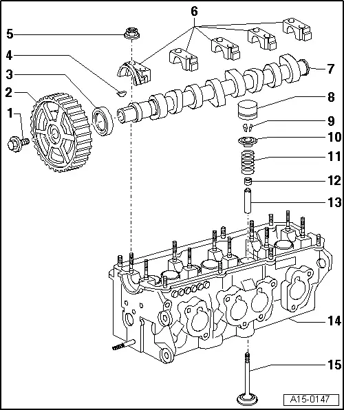
| 1 - | 100 Nm |
| q | To remove and install, use the Spanner -3415 -. |
| 2 - | Camshaft gear |
| 3 - | Sealing ring |
| q | Replace → Chapter. |
| 4 - | Key |
| q | Check firm fitting. |
| 5 - | 20 Nm |
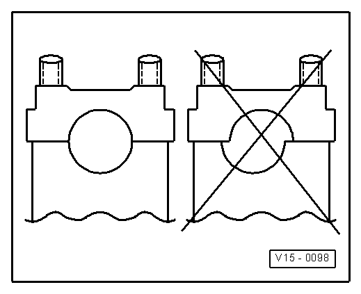
| 6 - | Bearing cover |
| q | Assembly position → Fig. |
| q | Assembly sequence → Chapter. |
| q | Grease the support surface of bearing cover 1 with the Sealing putty -AMV 174 004 01-. |
| 7 - | Camshaft |
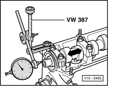
| q | Check axial clearance → Fig. |
| q | Remove and install → Chapter. |
| q | Measure radial clearance with “Plastigage”: Wear limit: 0.1 mm. |
| q | Runout: max. 0.05 mm. |
| 8 - | Hydraulic tappet |
| q | Do not invert. |
| q | With valve clearance hydraulic offsetting. |
| q | Check → Chapter. |
| q | Place with the contact surface facing down. |
| q | Check camshaft axial clearance before installing → Fig. |
| q | Lubricate contact surfaces. |
| 9 - | Keys |
| 10 - | Upper plate of valve springs |
| 11 - | Valve spring |
| q | Remove and install: Cylinder head removed: with the Compressor device -2037- installed: → Chapter. |
| 12 - | Valve rod oil seal |
| q | Replace → Chapter. |
| 13 - | Valve guide |
| q | Check → Chapter. |
| q | Repair guide with shoulder. |
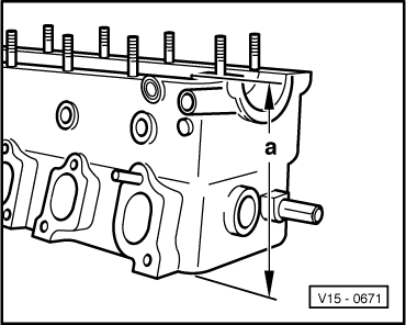
| 14 - | Cylinder head |
| q | Rework the sealing surface → Fig. |
| q | Grind valve seats → Chapter. |
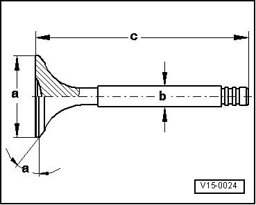
| 15 - | Valves |
| q | Do not grind; only seating is permitted. |
| q | Valve measures → Fig. |
 Note
Note
|
|
|
|
|
|
| Identification between cam pairs, intake and exhaust valve of cylinder 1 | |
| Cylinder 1 (BBX engine) | 050 P |
| Cylinder 1 (CFEA engine) | 06A M |
Note
|
|
| Measure | Intake valve | Exhaust valve | |
| Ø a | mm | 39,5 ± 0,15 | 32,9 ± 0,15 |
| Ø b | mm | 6,98 ± 0,007 | 6,96 ± 0,007 |
| c | mm | 91,85 | 91,15 |
| α | ∠° | 45 | 45 |
|
| Intake valve | Exhaust valve | ||
| Then opens | TDC | 6,2° | -------- |
| Then closes | BDC | 42,45° | -------- |
| Opens before | BDC | --------- | 35,8° |
| Then closes | TDC | --------- | 0,45° |