
Polo Mk4
| Fuel tank components with accessories and fuel filter - remove and install |

| 1 - | Lid fastening belt |
| q | Non-applicable for vehicles as of 20.01.2003. |
| 2 - | Fuel tank lid |
| 3 - | Sealing ring |
| q | Replace it if damaged. |
| 4 - | Fastening screw |
| 5 - | Fuel tank nozzle compartment lid set |
| q | With rubber bellows. |
| q | Removal and installation → Body - External assembly works; Rep. gr.55. |
| 6 - | Gravity valve |
| q | To remove, remove it from fuel tank nozzle, upwards. |
| q | Check valve passage continuity. |
| q | Perpendicular valve: open. |
| q | Valve inclined 45°: closed. |
| 7 - | Earth wire |
| q | Make sure it is well fastened. |
| 8 - | Vent tube |
| q | Make sure it is well fastened. |
| 9 - | Activated charcoal filter |
| q | Installation location: in the right rear wheel case. |
| 10 - | 10 Nm |
| 11 - | Vent tube |
| q | Secured to the activated charcoal filter. |
| q | Make sure it is well fastened. |
| 12 - | 25 Nm |
| 13 - | Fuel tank |
| q | Remove using the Gearbox jack or engine/gearbox assembly or VAG 1383A -EQ 7081-. |
| q | Remove and install → Chapter. |
| 14 - | Fastening straps |
| 15 - | Vent tube |
| q | Make sure it is well fastened. |
| 16 - | Clip |
| q | Make sure it is well fastened. |
| 17 - | Fuel filter |
| q | Installation position: the arrow indicates the flow direction. |
| 18 - | Outlet pipes |
| q | Black. |
| q | Make sure it is well fastened. |
| q | For fuel rail. |
| 19 - | Sealing ring |
| q | Replace when damaged. |
| 20 - | Sealing ring |
| q | Replace. |
| 21 - | Fuel pressure regulator |
| q | For BPA/CCRA engine in the Fuel pump (pre-supply pump) -G6-. |
| 22 - | 5 Nm |
| q | For fuel filter clamp. |
| 23 - | Sealing ring |
| q | Replace. |
| q | For installation, place it dry on fuel tank opening. |
| q | Lubricate with fuel only for installing the Fuel pump (pre-supply pump) -G6-. |
| 24 - | Fuel level indicator sensor -G- |
| q | Remove and install → Chapter. |
| 25 - | Fuel pump (pre-supply pump) -G6- |
| q | Remove and install → Chapter. |
| q | Clean screen filter, if dirty. |
| q | Check the Fuel pump (pre-supply pump) -G6- → Chapter. |
| q | Check the installation position in the fuel tank → Fig. |
| 26 - | Return pipes |
| q | Blue. |
| q | Fastened laterally to the fuel tank. |
| q | Make sure it is well fastened. |
| 27 - | Outlet pipes |
| q | Black. |
| q | Fastened laterally to the fuel tank. |
| q | Make sure it is well fastened. |
| 28 - | 80 Nm |
| q | Remove and install using the Wrench or VW 5321/7 -3217-. |
| 29 - | 10 Nm |
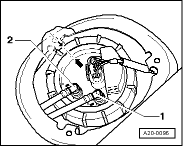
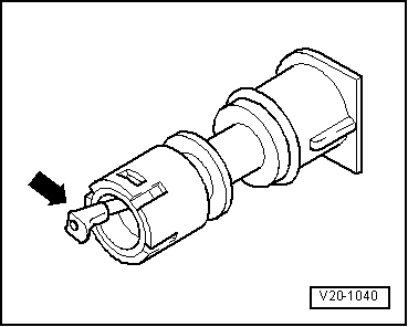
| 30 - | Vent valve |
| q | Check → Fig. |
| q | To remove, press the lock slightly inwards and remove the valve. |
 Note
Note
|
|