| –
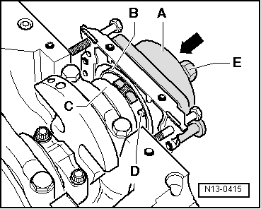
| Manually slide assembly body -A- in -arrow- direction until seal lip support ring -B- seats on crank shaft flange -C-. |

Note | Guide pin -D- of assembly device is introduced, during assembly, through a threaded hole of crank shaft. This way definitive rotor assembly position is determined. |
| –
| Keep assembly body in this position and manually tighten Allen bolts of assembly device. |
| –
| Thread six-sided nut -E- to threaded fuse until it touches assembly body -A-. |
|
|
|
