
Polo Mk4
|
 WARNING
 Note
Note
|
|
|
|
|
|
|
|
|
|
|
|
|
|
|
|
Note
|
|
 Caution
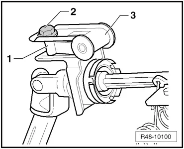
| Components | Tightening torque | ||
| Steering column earth strap | 4.5 ± 0.5 Nm | ||
| Bushing support for steering column fork | 7 Nm | ||
Steering box steering column
| 20 Nm + 90° | ||
Lower fastening of steering column (M8 x 85)
| 20 Nm | ||
Lower fastening of steering column (M6 x 63)
| 9.7 ± 1 Nm | ||
Upper steering column fastening
| 23 ± 2 Nm |